

Catalyzed coal powder burning process, coal powder catalyzing burner and coal powder burning catalyst
A catalytic burner and pulverized coal combustion technology, applied in the field of coal combustion and pulverized coal combustion, can solve the problems of not being able to be fully equipped with dust removal, desulfurization, and denitrification devices, low coal combustion efficiency, waste of coal resources, etc. Economic benefits and environmental protection benefits, the effect of reducing waste of coal resources and reducing pollutant emissions
- Summary
- Abstract
- Description
- Claims
- Application Information
AI Technical Summary
Problems solved by technology
Method used
Image

Examples
Embodiment 1
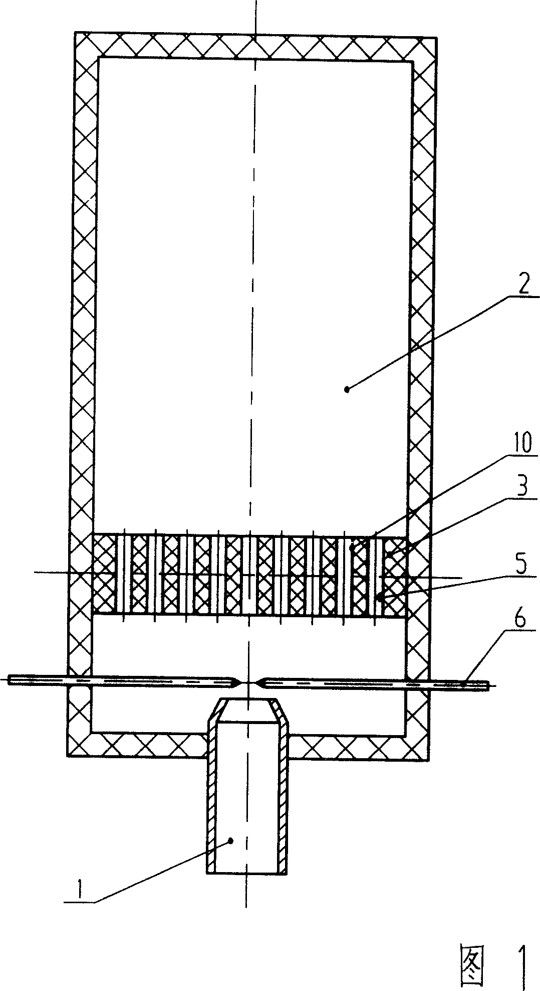
[0038] The principle diagram of the pulverized coal catalytic combustion method described in this embodiment is shown in FIG. 1 .
[0039] The pulverized coal catalytic combustion method described in this embodiment is to realize in a boiler, and a combustion nozzle 1 is installed on one end of boiler combustion chamber 2, and a honeycomb-shaped guide combustion plate 3 is installed in the middle part of combustion chamber 2, on it There are honeycomb-shaped diversion holes 5, and an igniter 6 is installed between the burner nozzle 1 and the honeycomb-shaped diversion combustion plate 3.
[0040] The pulverized coal combustion catalyst 10 is composed of AL2O3 85%, MnO2 3%, CuO3%, TiO2 2%, Nio2 3%, and mixed rare earth 5% by weight percentage. After the above ingredients are mixed with twice the deionized water, they are ball milled by a ball mill After 48-72 hours, it becomes gel, add deionized water to dilute the slurry, put the honeycomb-shaped deflector combustion plate 3 i...
Embodiment 2
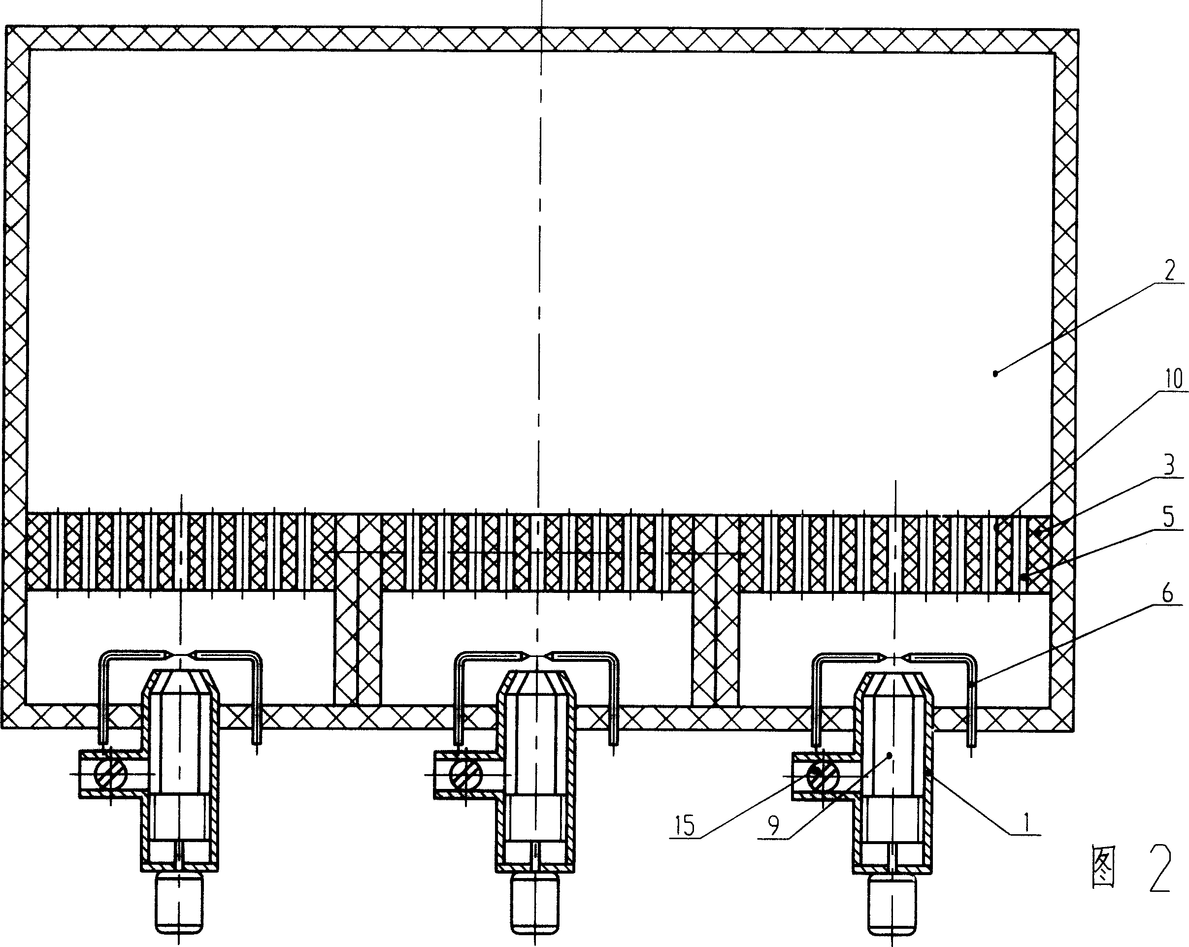
[0043] The principle of the pulverized coal catalytic combustion method described in this embodiment is shown in FIG. 2 .
[0044] The pulverized coal catalytic combustion method described in this embodiment is realized in a general industrial kiln. Three combustion nozzles 1 are arranged on the side of the combustion chamber 2 of the industrial kiln. Before the combustion nozzle 1, an igniter 6 and a honeycomb guide are installed. flow burner plate3. A movable nozzle core 9 driven by an electric motor is installed in the cavity of the combustion nozzle 1 . According to the method in Example 1, the pulverized coal combustion catalyst 10 is deposited on the surface layer of the honeycomb guide combustion plate 3 .
[0045] Coal is pulverized into coal powder of about 200 meshes, mixed with air to form gaseous fuel, and sent to combustion chamber 2 through combustion nozzle 1 for combustion. The working process is basically the same as that described in embodiment 1. The differe...
Embodiment 3
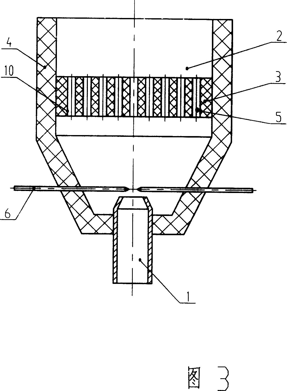
[0047] The principle diagram of the pulverized coal catalytic combustion method described in this embodiment and the structural schematic diagram of the pulverized coal catalytic burner are shown in FIG. 3 , and the structural schematic diagrams of the honeycomb flow-guiding combustion plate 3 are shown in FIG. 4 and FIG. 5 .
[0048] The pulverized coal catalytic combustion method described in this embodiment is realized in a pulverized coal catalytic burner. The pulverized coal catalytic burner is composed of a combustion nozzle 1, a combustion chamber 2 and a honeycomb-shaped diversion combustion plate 3, etc. The rear portion of the combustion chamber 2 is a cone, and the front portion is a cylinder, and the combustion nozzle 1 is installed in the middle of the rear portion of the combustion chamber 2 . A refractory layer 4 made of refractory material is provided on the inner wall of the combustion chamber 2 . In the middle of the combustion chamber 2, a honeycomb guide c...
PUM
| Property | Measurement | Unit |
|---|---|---|
| Granularity | aaaaa | aaaaa |
| Thickness | aaaaa | aaaaa |
| Equivalent diameter | aaaaa | aaaaa |
Abstract
Description
Claims
Application Information