Method of treating sewage by composite vertical down flow artificial wet field and treatment system thereof

A technology of constructed wetlands and treatment systems, applied in the direction of sustainable biological treatment, chemical instruments and methods, biological water/sewage treatment, etc., to improve the removal effect, prevent backwater phenomenon, and improve the removal capacity

Active Publication Date: 2007-10-17
SOUTH CHINA AGRI UNIV
View PDF0 Cites 13 Cited by
  • Summary
  • Abstract
  • Description
  • Claims
  • Application Information

AI Technical Summary

Problems solved by technology

[0003] In order to overcome the deficiencies of the existing composite vertical flow artificial wetland treatment method for sewage, the primary purpose of the present invention is to provide a composite vertical downward flow artificial wetland treatment method for sewage with low treatment cost, small footprint, and good nitrogen and phosphorus removal effects. method

Method used


Image

  • Method of treating sewage by composite vertical down flow artificial wet field and treatment system thereof
  • Method of treating sewage by composite vertical down flow artificial wet field and treatment system thereof
  • Method of treating sewage by composite vertical down flow artificial wet field and treatment system thereof

Examples


Embodiment 1

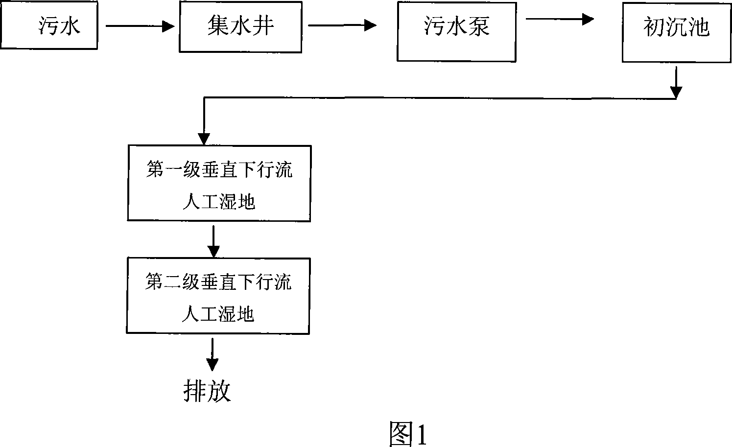
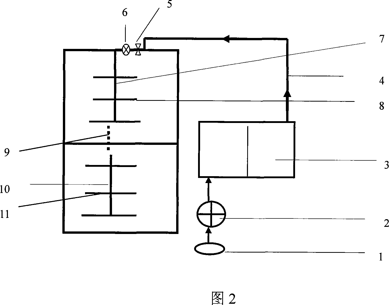
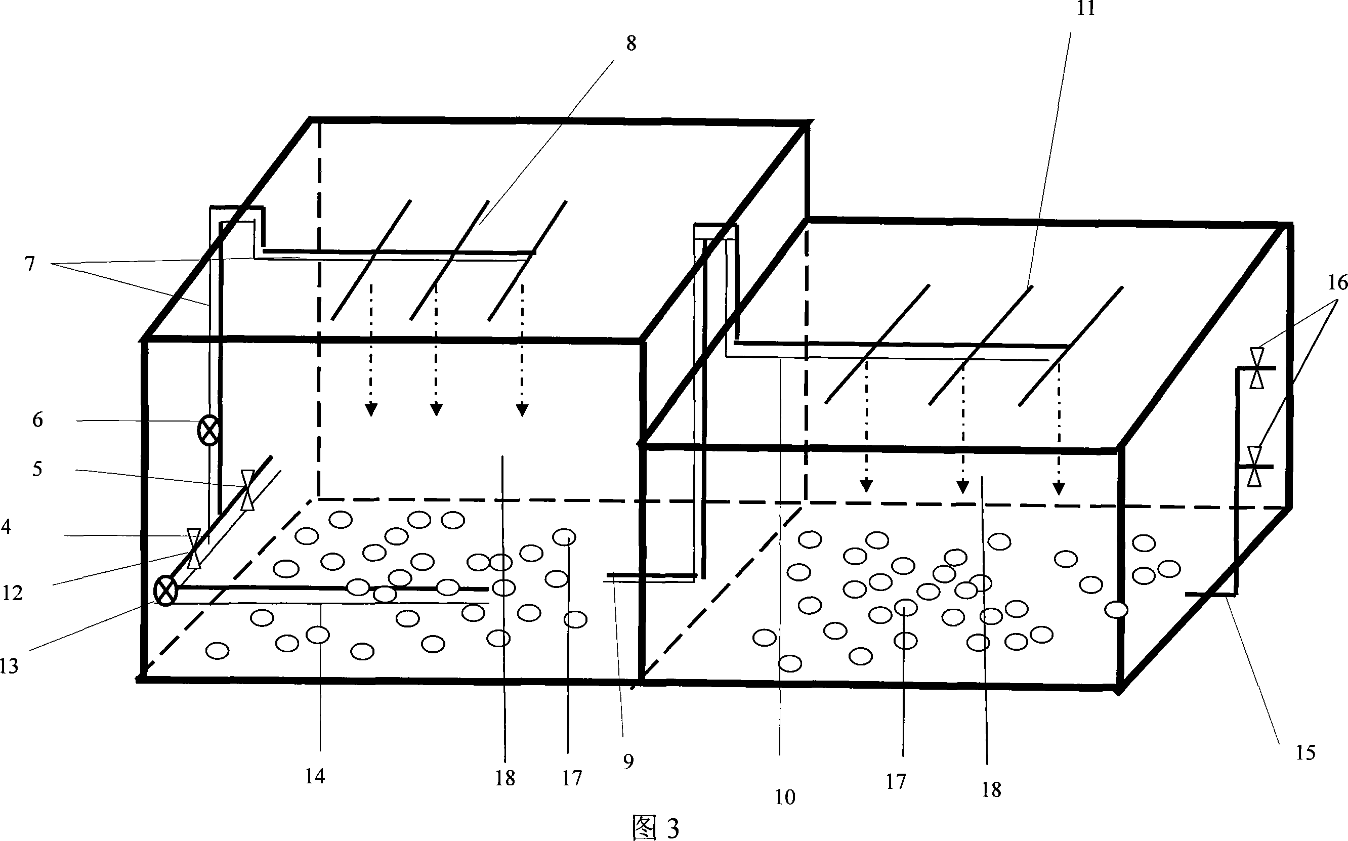
[0029] The composite vertical downflow artificial wetland treatment system of the present invention comprises the primary sedimentation tank 3, the first vertical downflow artificial wetland and the second vertical downflow artificial wetland, the primary sedimentation tank 3, the first vertical downflow artificial wetland, the second Unit structures such as level vertical downflow constructed wetlands are connected by pipes. The primary sedimentation tank 3 is connected to the first-level vertical downflow constructed wetland through the sewage pipe 4, and the second-level vertical downflow constructed wetland is connected to the first-level vertical downflow constructed wetland through the second-level vertical downflow constructed wetland. Water pipe 9 links to each other.

[0030] The vertical downflow constructed wetland system consists of a bed body, a "king" shaped water distribution pipe, and a treatment medium. The bed wall of the bed body is made of non-seepage mater...

Embodiment 2

[0044] In this embodiment, the matrix filled in the matrix layer of the first-stage vertical downflow constructed wetland is melonite (0.5-1.0 cm in diameter). The matrix filled in the matrix layer of the second vertical downflow constructed wetland is also blast furnace slag (0.1-0.5cm in diameter).

[0045] The system treatment effects (mg / L, %) in this embodiment are shown in Table 1, Table 2, Table 3, Table 4 and Table 5. Table 1, Table 2, Table 3, Table 4 and Table 5 respectively show the COD and BOD in sewage after the urban sewage is treated by the composite vertical downflow constructed wetland system 5 , NH 4 + -N, TP, TN concentration changes.

Embodiment 3

[0047] In this example, when the hydraulic load is 0.6m 3 / m 2 At d, the matrix layer of the first-stage vertical downflow constructed wetland is filled with a matrix volume ratio of blast furnace slag (0.1-0.5cm in diameter) and medium-coarse sand (0.05-0.2cm in diameter) fully mixed matrix with a volume ratio of 1:1 , The second-stage vertical downflow constructed wetland matrix layer is filled with coal ash (0.1-2.0cm in diameter) as filler.

[0048] The hydraulic loads were 1.2m 3 / m 2At d, the matrix layer of the first-stage vertical downflow constructed wetland is filled with a matrix volume ratio of 1:3 blast furnace slag (diameter 0.1-0.5cm) and medium-coarse sand (diameter 0.05-0.2cm) fully mixed mixed matrix , The second-stage vertical downflow constructed wetland matrix layer is filled with coal ash (0.1-2.0cm in diameter) as filler.

[0049] The hydraulic loads were 2.4m 3 / m 2 At d, the matrix layer of the first-stage vertical downflow constructed wetland is...


PUM

PropertyMeasurementUnit
heightaaaaaaaaaa
diameteraaaaaaaaaa
diameteraaaaaaaaaa

Abstract

The invention discloses a sewage treatment method of composite vertical letdown stream artificial wetland, sewage is processed through two-stage serial vertical letdown stream artificial wetland in the method, the two-stage vertical letdown stream artificial wetland comprises a bed, E-shape structure water distribution pipe and processing medium, internal carbon source waste pipe distributed at the bottom of a first stage vertical letdown stream artificial wetland, sewage enter uniformly into the bottom of the first stage vertical letdown stream artificial wetland from the top thereof via the E-shape structure water distribution pipe, then the processed sewage mixed with internal carbon source sewage is processed in the second stage vertical letdown stream artificial wetland. The invention has advantages of low processing cost, small accommodation area and good denitrification dephosphorization effect.

Description

technical field [0001] The invention belongs to the field of sewage treatment, and in particular relates to a method for treating sewage in a composite vertical downflow artificial wetland and a treatment system thereof. Background technique [0002] At present, the sewage complex vertical flow artificial wetland treatment method is mainly the combination of downflow and upflow. It is composed of a descending pool and an ascending pool. There is a partition wall in the middle of the two pools, and the bottom is connected. In the center of the surface of the descending pool is a perforated water distribution pipe with small holes drilled in the lower half, so that the water inflow can be evenly distributed to the surface of the wetland. The water in the upward pool, the upward pool uses the "H" type pipeline collection system to discharge the water. Both the downstream and upstream ponds are filled with sand and gravel of a certain size as the tr...

Claims


Application Information

Patent Timeline
Patent Type & Authority Applications(China)
IPC IPC(8): C02F3/32C02F3/10
CPCY02W10/10
Inventor 崔理华朱夕珍董梅张宪宁吴属连
Owner SOUTH CHINA AGRI UNIV
Why Eureka
Try Eureka