Water source heat pump heat-supply device for oil field well mouth

A water source heat pump and heating device technology, applied in the direction of heating devices, geothermal power generation, and other non-combustion heat generation, can solve energy waste and other problems, achieve no environmental pollution, solve energy waste and operation safety hazards, and be easy Achieved effect

Inactive Publication Date: 2007-10-17
靖洪铭 +1
View PDF3 Cites 7 Cited by
  • Summary
  • Abstract
  • Description
  • Claims
  • Application Information

AI Technical Summary

Problems solved by technology

[0003] The purpose of the present invention is to provide a water source heat pump heating device at the wellhead of an oil field, which has a reasonable overall structure design and is easy to operate, and can fundamentally solve the problems of energy waste in the prior art and limit the development of water source heat pump heat collection technology. , using renewable energy, no environmental pollution, significantly saving primary energy, significantly reducing operating costs and maintenance costs, and improving oil well operation stability and safety reliability

Method used


Image

  • Water source heat pump heat-supply device for oil field well mouth
  • Water source heat pump heat-supply device for oil field well mouth
  • Water source heat pump heat-supply device for oil field well mouth

Examples


Embodiment Construction

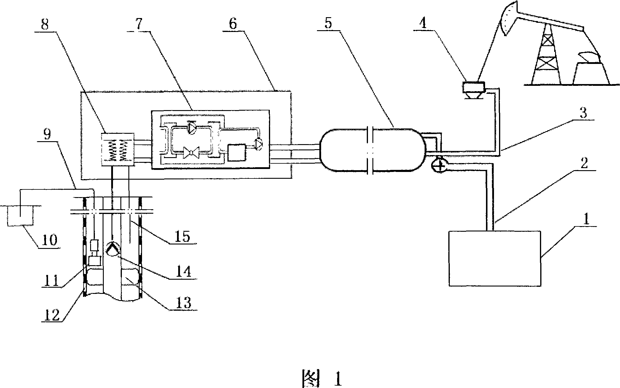
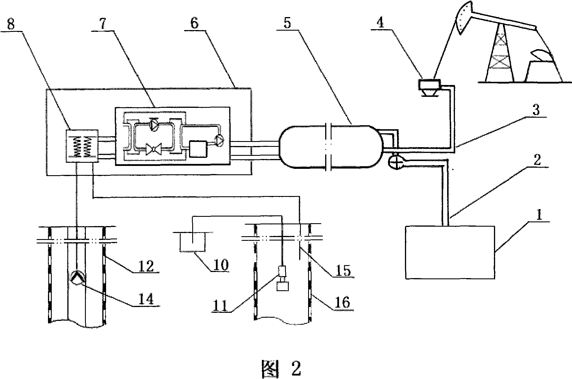
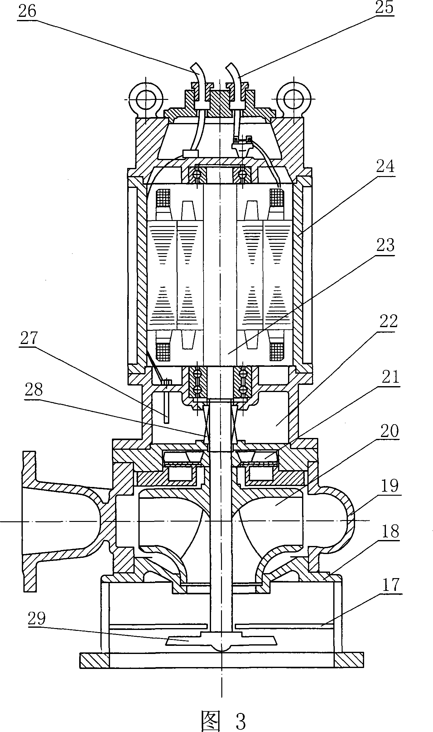
[0011] The specific structure of the present invention will be described in detail according to FIGS. 1 to 3 . The device adopts the mature heat pump heat collection technology and the heat collection method of the common heat exchanger to replace the traditional water jacket furnace heating device of the existing oil well. It can be designed according to the specifications and use needs of the heat collection well of the existing water source heat pump unit into type I and type II structures. Figure 1 shows a schematic diagram of the I-type structure. The automatic control powerful sewage pump is installed at the bottom of the recharge water layer in the well pipe where the heat collection well is a pumping well. What Fig. 2 shows is type II structure schematic diagram). It includes a heat pump unit 7 assembled in the machine room 6, a water source heat exchanger 8, a medium heater 5, a wellhead medium transmission pipe 3 connected to the wellhead 4 of the pumping unit, a he...


PUM


Abstract

A water-source heat pump heating device used for oil field wellhead includes wellhead medium transmission tube, heat exchange medium output tube for connecting gathering station, water-source heat interchanger connected to water-source heat pump group, pumping submersible pump and recharge water tube which are assembled in well tube of heat collector well. The technical points includes that: the wellhead medium transmission tube and the heat exchange medium output tube connected to the gathering station are respectively connected to heat exchange medium inlet end and outlet end of the medium heater, and high temperature cycle pipeline of the heat pump group is connected to heating pipe in the medium heater, double-channel non-plug impeller comprised by main, vice impellers and automatic control powerful pollution discharge pump of fixed stirrer assembled at terminal end of motor shaft are arranged at bottom of the recharge water level in well tube of the heat collection well, outlet end of the pump is connected to sedimentation pond outside the well tube. The invention has reasonable design, easy operation, and can save primary energy and improve stability and safety of the oil well.

Description

technical field [0001] The invention relates to a heating and temperature-raising device for the mixed medium of crude oil, water and gas collected in oil wells, in particular to an oil field wellhead using water source heat pump heat collection technology and heat exchangers to replace the water jacket furnace to heat the mixed medium collected in oil wells Water source heat pump heating device. It can also be used as a cold and heat source for other temperature adjustment places. Background technique [0002] At present, the mixed medium of crude oil, water, and gas collected at the wellhead of the oil field and its gathering and transportation station (combined station) needs to be heated up to prevent the mixed medium flowing through the wellhead device or the gathering and transportation station from sticking. Or freeze to ensure the smooth flow of oil pipelines. Traditional heating devices generally use coal-fired, oil-fired, gas-fired water jacket furnaces or electr...

Claims


Application Information

Patent Timeline
Patent Type & Authority Applications(China)
IPC IPC(8): F24J3/08
CPCY02E10/10
Inventor 靖洪铭靖淑媛
Owner 靖洪铭
Why Eureka
Try Eureka