Hollow four-side connector

A hollow, conductive surface technology, applied in the direction of connection, conductive connection, electrical component connection, etc., can solve the problems of excessive conductor overcurrent, short circuit to ground, fire, etc., to increase heat dissipation space, increase the loading surface of the end Great, heat-reducing effect

Inactive Publication Date: 2007-10-17
罗志昭
View PDF1 Cites 2 Cited by
  • Summary
  • Abstract
  • Description
  • Claims
  • Application Information

AI Technical Summary

Problems solved by technology

[0002] The existing conductive pipe busbar joint (patent number: 01215457.1) has the following disadvantages in the actual installation process: since the conductive pipe busbar is circular, it is necessary to install conversion fittings during the connection with the equipment, from a round surface to a plane, through Rectangular conductors to connect with other equipment
1. The connection between the pipe busbar and the equipment needs to be equipped with conversion fittings, which is costly, wastes materials, and consumes energy
2. The original joint has only two conductive planes, the cross-sectional area is small, and the conductors are split. When the current is transmitted, there will be uneven current distribution. One of the conductive plane conductors has a small overcurrent, and the other conductive plane conductor has overcurrent If it is too large, the side with high overcurrent will generate high temperature
3. The connection between the end of the pipe busbar and the conversion fitting will generate contact resistance. Due to the existence of contact resistance, in the case of high current transmission, the end of the pipe busbar and the conversion fitting will generate excessive heat. The greater the heat, the higher the resistance , the more serious the heat is, the higher the temperature will cause the pipe busbar to be blown, short circuit between phases, short circuit to ground or cause a fire and cause a greater accident

Method used


Image

  • Hollow four-side connector
  • Hollow four-side connector
  • Hollow four-side connector

Examples


Embodiment Construction

[0009] The specific embodiments of the present invention will be further described below in conjunction with the accompanying drawings.

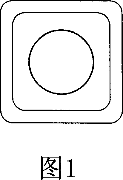
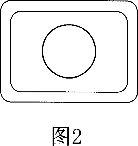
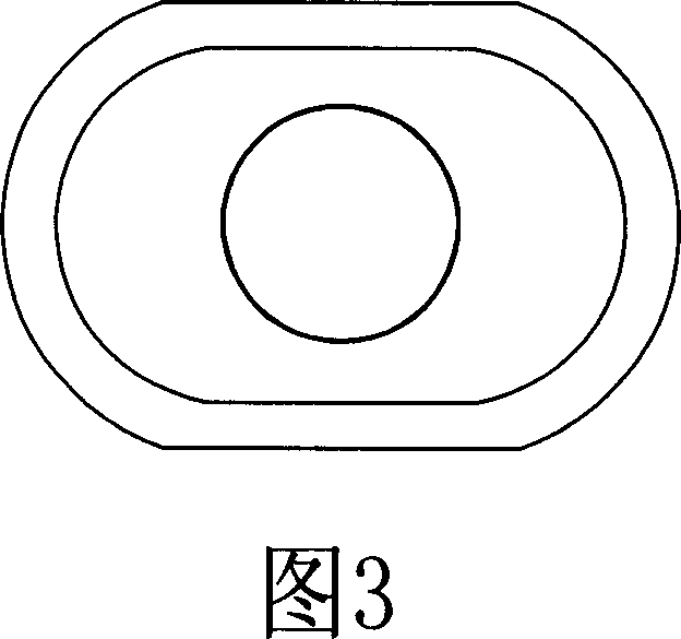
[0010] As shown in Figure 1, the hollow four-sided joint of the present invention is the end pipe diameter of the copper or aluminum pipe busbar and the copper composite pipe busbar (composite steel pipe or aluminum pipe in the copper pipe) with a diameter of Φ30mm to 500mm and a wall thickness of 1mm to 30mm. Use a punch or hydraulic press to stamp and form 4 copper and aluminum conductive surfaces, and configure a suitable mold to process the conductive surfaces (square, rectangular, 2-plane oval) according to the actual current carrying capacity requirements and the requirements of the busbar pipe diameter. There is a certain heat dissipation space distance between the 4 copper and aluminum conductive planes, and then the 4 copper and aluminum conductive planes formed by stamping are fastened with rectangular conductors or soft connections...


PUM


Abstract

The pipe bus end calibre of the inventive hollow four-side joint copper, aluminium pipe bus and copper multiple tube bus (steel pipe or aluminium pipe is claded in the copper pipe) is moulded into four hollow copper and aluminum conducting surfaces by a punching technology. The suitable mould are configured according to actual carrying capacity requirement and the requirement of bus calibre, to process the conducting surfaces (shapes such as a square, a rectangle and two plane ellipse). Since it is an integrated one withou link bit and contacting resistance, thus ensuring the end of the bus will not have a high temperature, and will have safe operation.

Description

technical field [0001] The hollow four-sided joint of the present invention is especially suitable for connecting the bus bar of the conductive pipe and the equipment for conveying power frequency and large current. Large current carrying capacity, low temperature rise, high mechanical strength, and improved operating safety factor. Background technique [0002] The existing conductive pipe busbar joint (patent number: 01215457.1) has the following disadvantages in the actual installation process: since the conductive pipe busbar is circular, it is necessary to install conversion fittings during the connection process with the equipment, from a round surface to a plane, through Rectangular conductors connect with other devices. 1. It is necessary to install conversion fittings to connect the pipe busbar to the equipment, which is costly, wastes materials and consumes energy. 2. The original joint has only two conductive planes, the cross-sectional a...

Claims


Application Information

Patent Timeline
Patent Type & Authority Applications(China)
IPC IPC(8): H01R4/46H01R11/00
Inventor 罗志昭
Owner 罗志昭
Why Eureka
Try Eureka