
A multi-link transfer control method

A transmission control and multi-link technology, applied in transmission systems, digital transmission systems, electrical components, etc., can solve the problems of increasing the complexity of transmission control and not taking into account the lithography device.

Inactive Publication Date: 2007-10-17
SHANGHAI MICRO ELECTRONICS EQUIP (GRP) CO LTD
View PDF0 Cites 10 Cited by
  • Summary
  • Abstract
  • Description
  • Claims
  • Application Information

AI Technical Summary

Problems solved by technology

[0005] Some existing transmission control methods, such as the general standard TCP / IP network protocol method, cannot take into account these requirements in the lithography device, and the TCP / IP network uses a seven-layer protocol, and the control of the physical layer needs to be controlled by two or Realization of more than two transmission media increases the complexity of transmission control

Method used


Image

  • A multi-link transfer control method

Examples


Embodiment 1

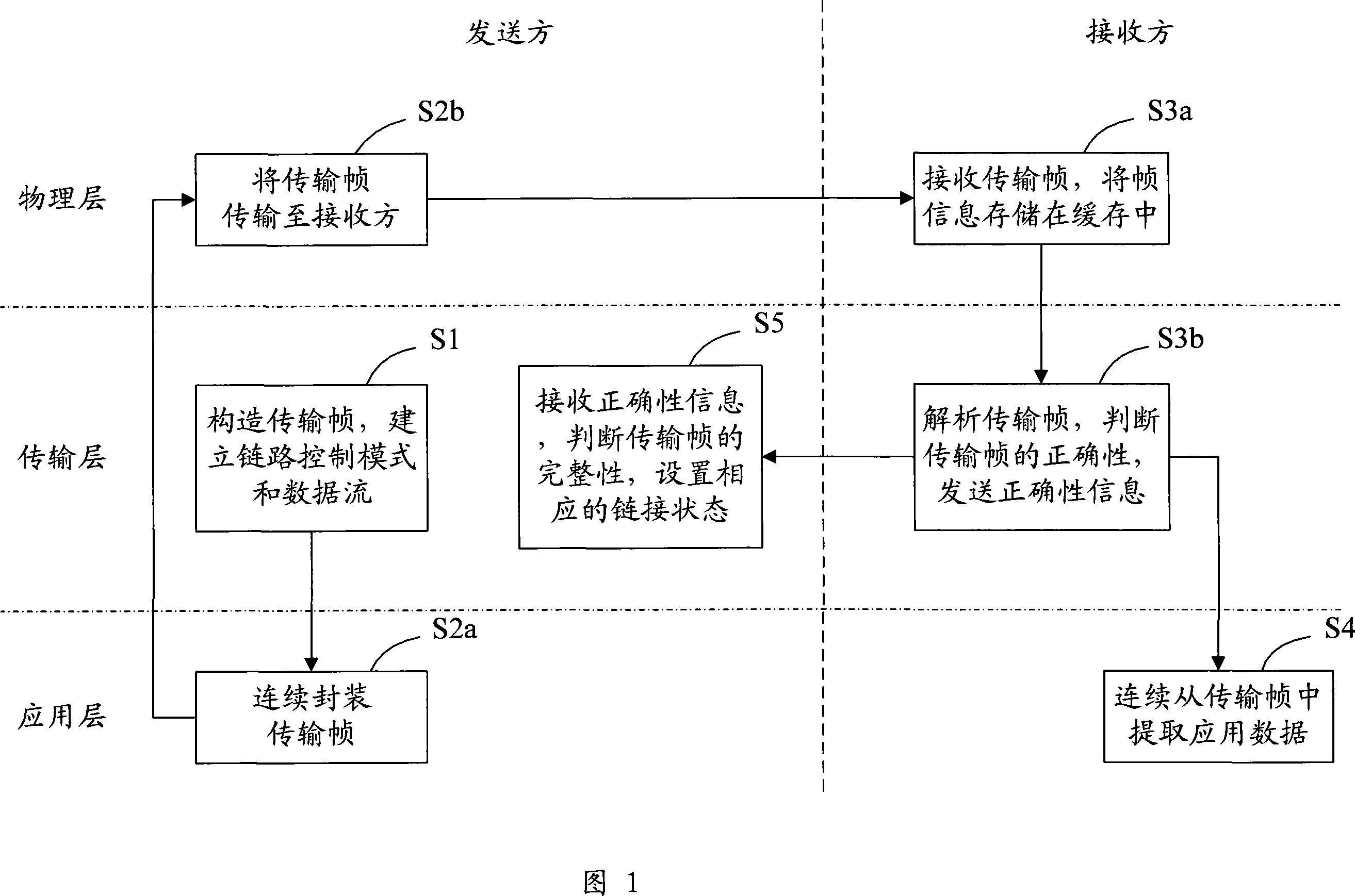
[0027] In photolithography devices and other industrial devices, the link management control method of point-to-point data transmission frames is used in occasions that require high link speed. The specific control process steps are as follows:

[0028] a1. The sender constructs a frame;

[0029] a2. The sender reads the frame information, which includes: frame start field, frame length, start address, identification code, control code, data and its calculation check code or error correction mask, frame end field, etc. Composed frame information, and the frame information except the frame start field and end field is sent out from the sending interface after verification or error correction coding;

[0030] a3. The receiver receives the frame information composed of frame start field, frame length, start address, identification code, control code, data and its calculated check code or error correction mask, frame end field, etc. from the receiving port, and Perform check cal...

Embodiment 2

[0033] In lithography devices and other industrial devices, the link management control method of splicing broadcast transmission frames is usually used in the data collection process, and multiple data frames are spliced ​​together to form a complete data link, realizing multiple acquisitions Data splicing and high-speed transmission. The specific control process steps are as follows:

[0034] b1. The first sender / receiver assembles the frame;

[0035]b2. The first sender / receiver reads the frame information, which includes: frame start field, frame length, start address, identification code, control code, data and its calculation check code or error correction mask, frame end Field and other components or a part of frame information, and the frame information except the frame start field and end field is sent out from the sending interface after verification or error correction coding;

[0036] b3. The work of the second sender / receiver to receive the data frame from the f...

Embodiment 3

[0044] In photolithography devices and other industrial devices, the specific control flow steps of the link management control method for non-spliced ​​broadcast transmission frames are compared with Embodiment 2, there is no step b4, and step b5 does not have a splicing receiving part, and the remaining specific control flow steps It is completely consistent and will not be repeated here.


PUM


Abstract

The present invention discloses a multi-link transmission control method for achieving a transmission control between a sender and a receiver through a control structure composed of a physical layer, a transport layer and an application layer. Said method comprises the following steps: the sender constituting transmission frames through the transport layer and setting up link control mode and data stream; the transmission frames being encapsulated continuously through the application layer and being transmitted to the receiver through the physical layer; the receiver receiving the transmission frames through the physical layer, storing the frame information, resolving the transmission frames through the transport layer, judging the correctness of the transmission frames constituted according to the transmission frame information resolved, and returning the correctness information to the receiver; the receiver extracting continuously application data from the transmission frames constituted by the sender, through the application layer; the sender receiving the correctness information through the transport layer, judging the integrality of the transmission frames based on the received correctness information, and setting corresponding linking states. By adapting said method, sampling control, collection transmission control, data exchange control and data communication transmission control of signals can be completed with a super high velocity.

Description

technical field [0001] The invention relates to data transmission control, in particular to a multi-link transmission control method. Background technique [0002] In industrial devices, due to the need for high precision and high productivity, a large number of control systems for high-speed real-time signal sampling, data acquisition, data exchange and communication transmission are distributed. These systems require us to use various methods to realize the control of sensor signal sampling control, data acquisition control, data exchange control and data transmission communication. Devices that require this control include: integrated circuit manufacturing lithography devices, liquid crystal panel lithography devices, MEMS / MOMS lithography devices, advanced packaging lithography devices, printed circuit board lithography devices, printed circuit board processing devices, and printed circuit board Device placement devices, etc. [0003] In lithography equipment, multiple...

Claims


Application Information

Patent Timeline
IPC IPC(8): H04L29/08H04L12/56H04L1/00H04L12/70
Inventor 李焕炀陈勇辉周畅严天宏
Owner SHANGHAI MICRO ELECTRONICS EQUIP (GRP) CO LTD
Learn More