A package method for double-side silicon-glass solar cell assembly

A solar cell module and double-sided glass technology, which is applied in the direction of electrical components, semiconductor devices, circuits, etc., can solve the problem that the yield rate of the product is competitive with ordinary components, the high process cost is not suitable for large-scale production, and the packaging process has technical bottlenecks and other problems, to achieve the effect of avoiding cell fragments, strong impact resistance, and optimizing the lamination process

Inactive Publication Date: 2007-10-24
SOUTH CHINA UNIV OF TECH
View PDF0 Cites 24 Cited by
  • Summary
  • Abstract
  • Description
  • Claims
  • Application Information

AI Technical Summary

Problems solved by technology

[0002] Double-sided glass modules are beautiful and have a wide range of applications, but there are still technical bottlenecks in the packaging process. The double-sided glass solar cell modules launched by domestic and foreign photovoltaic companies still cannot compete with ordinary modules in terms of production cost, product yield and product weather resistance. compete with
At present, companies such as Kyocera in Japan and Shell in Germany use glue potting to package double-sided glass components. This process is relatively mature and can produce curved glass components, but the process cost is very high and is not suitable for mass production.
[0003] Double-sided glass solar cells are packaged using the ordinary solar cell module lamination packaging process. Since the rigid glass is used instead of the flexible TPE used in ordinary modules as the backsheet material of the module, the process of double-sided glass lamination packaging is due to two layers The extrusion of rigid glass is prone to air bubbles, displacement, solar cell cracks, and glass breakage. For this reason, a German component equipment company has launched a lamination equipment with a cooling system, which can solve the problem of bubbles in double-sided glass components, but The lamination cycle of this process is long, and the investment in equipment is very large
[0004] In recent years, the photovoltaic industry at home and abroad has developed rapidly. Several domestic solar cell module packaging manufacturers are also committed to the research of double-sided glass solar cell module packaging, and have launched double-sided glass solar modules at some domestic exhibitions. Some modules have a small amount of Bubbles, and high prices, have not yet fully entered the market

Method used


Image

  • A package method for double-side silicon-glass solar cell assembly
  • A package method for double-side silicon-glass solar cell assembly
  • A package method for double-side silicon-glass solar cell assembly

Examples


Embodiment 1

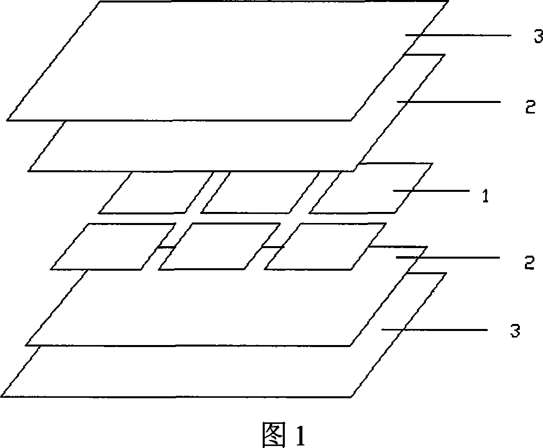
[0019] As shown in Figure 1, first lay a piece of low-iron tempered glass 3 on the table, and spread a single layer of EVA film 2 with a thickness of 0.3mm on it, and put the series and parallel solar cell strings 1 on the EVA film. 2 Above, a single layer of EVA film 2 with a thickness of 0.3mm and low-iron tempered glass 3 are also laid on the solar cell string 1 to form a 5-layer structure of 3-2-1-2-3; Then use polymer materials to perform specific treatment on the above five-layer structure; then set the preheating temperature of the laminator to 70℃, when the temperature of the heating plate of the laminator reaches this temperature, put the above-mentioned processed five-layer structure into In the laminator, the upper cover of the laminator is combined, and the lower chamber of the laminator is evacuated while the upper chamber is inflated to pressurize the laminated battery; the laminating temperature of the laminator is set to 140℃, The lamination time at temperature is ...

Embodiment 2

[0021] As shown in Figure 1, first lay a piece of low-iron tempered glass 3 on the table, and lay a single layer of EVA film 2 with a thickness of 0.3mm on it, and put the series and parallel solar cell strings 1 on the EVA film 2. Above, two layers of EVA film 2 with a thickness of 0.3mm and low-iron tempered glass 3 are also sequentially stacked on the solar cell string 1 to form a 5-layer structure of 3-2-1-2-3; Use polymer materials to perform specific treatment on the above five-layer structure; then set the preheating temperature of the laminator to 70℃, when the temperature of the heating plate of the laminator reaches this temperature, put the above-treated five-layer structure into the layer In the press, the upper cover of the laminator is combined, and the lower chamber of the laminator is evacuated while the upper chamber is inflated to pressurize the laminated battery; the laminating temperature of the laminator is set to 140 ℃, at this temperature The lower laminatio...

Embodiment 3

[0023] As shown in Figure 1, first lay a piece of low-iron tempered glass 3 on the table, and spread a single layer of EVA film 2 with a thickness of 0.3mm on it, and put the series and parallel solar cell strings 1 on the EVA film. 2 Above, three layers of EVA film 2 with a thickness of 0.3mm and low-iron tempered glass 3 are also sequentially stacked on the solar cell string 1 to form a 5-layer structure of 3-2-1-2-3; Then use polymer materials to perform specific treatment on the above five-layer structure; then set the preheating temperature of the laminator to 70℃, when the temperature of the heating plate of the laminator reaches this temperature, put the above-processed five-layer structure into In the laminator, the upper cover of the laminator is combined, and the lower chamber of the laminator is evacuated while the upper chamber is inflated to pressurize the laminated battery; the laminating temperature of the laminator is set to 140°C. The lamination time at temperatur...


PUM


Abstract

The related package method for double-face glass crystal silicon solar cell assembly comprises: from top to bottom, stacking a glass-EVA film-solar cell-EVA film-glass structure with the serial solar cell, glass, and EVA film; treating the five-layer structure with special macromolecular material; when heating the cell layer-press machine to 70Deg, putting the five-layer structure into the machine for pressing; setting the machine temperature as 125-145Deg for 15-25min; then, balancing the gas pressure of machine lower cavity with outer atmosphere, and taking out the product. This invention overcomes the damage to product.

Description

Technical field [0001] The invention relates to a packaging method for double-sided glass crystal silicon solar cell components, which can be used for photovoltaic building integration. Background technique [0002] Double-sided glass modules are beautiful and have a wide range of applications. However, there are still technical bottlenecks in the packaging process. The production cost, product yield and weather resistance of the double-sided glass solar cell modules launched by photovoltaic companies at home and abroad are still not comparable to ordinary modules. Compete. At present, Japanese companies such as Kyocera and German Shell use glue-filling methods to encapsulate double-sided glass components. This process is relatively mature and can produce curved glass components, but the process cost is very high and not suitable for mass production. [0003] The double-sided glass solar cell is encapsulated by the ordinary solar cell module lamination and packaging process. Beca...

Claims


Application Information

Patent Timeline
Patent Type & Authority Applications(China)
IPC IPC(8): H01L31/18
CPCY02P70/50
Inventor 王磊张臻张正国方玉堂高学农
Owner SOUTH CHINA UNIV OF TECH
Why Eureka
Try Eureka