Soft switching phase-shift full bridge circuit

A full-bridge circuit and phase-shifting technology, applied in the field of phase-shifted full-bridge circuits, can solve the problems of short circuit, difficult zero-voltage switching, and incomplete reverse recovery of the rectifier diode on the secondary side of the transformer 70.

Inactive Publication Date: 2007-10-24
ACBEL POLYTECH INC
View PDF0 Cites 24 Cited by
  • Summary
  • Abstract
  • Description
  • Claims
  • Application Information

AI Technical Summary

Problems solved by technology

Although this design can effectively reduce the voltage spikes of the rectifier diodes on the secondary side of the transformer 70 due to reverse recovery, there are still problems in the line such as large loss of the added inductance and serious loss of duty cycle, and the secondary side of the transformer 70 The reverse recovery of the side rectifier diode has not been completely improved
[0007] It can be seen from the above that the existing phase-shifting full-bridge circuit generally has problems such as increased line loss after adding a resonant inductance and the reverse recovery problem of the rectifier diode has not been completely improved. In addition, the lagging bridge arm 72 of the full-bridge circuit It is not easy for the transistors M3 and M4 to realize zero-voltage switching, because after the transistors are cut off, the secondary side of the transformer 70 is short-circuited, and the load current reflected to the primary side does not participate in the parasitic capacitance C3 and C4 on the transistors M3 and M4. Charging and discharging, relying only on the energy stored in the leakage inductance of the transformer 70, it is difficult for the two transistors M3 and M4 to achieve zero-voltage switching
[0008] The above-mentioned existing phase-shifting full-bridge circuit obviously still has inconvenience and defects in structure and use, and needs to be further improved urgently.
In order to solve the problems existing in the phase-shifting full-bridge circuit, relevant manufacturers have tried their best to find a solution, but no suitable design has been developed for a long time, and there is no suitable structure for general products to solve the above problems. , this is obviously a problem that relevant industry players are eager to solve

Method used


Image

  • Soft switching phase-shift full bridge circuit
  • Soft switching phase-shift full bridge circuit
  • Soft switching phase-shift full bridge circuit

Examples


no. 1 example

[0086] Except the aforementioned first embodiment, the present invention can be realized by other variable designs:

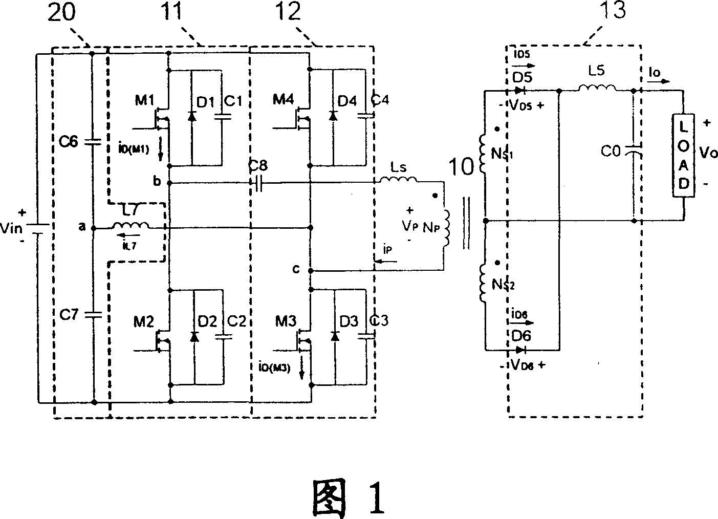
[0087] As shown in Figure 13, its basic structure is the same as that of the first embodiment, and it is emphasized that: the resonant inductance Ls connected in series on the primary side of the transformer 10 can be an independent inductance element, or can be formed by the leakage inductance of the transformer 10, etc. The reason is that the resonant inductance Ls is an inductance with a relatively small inductance.

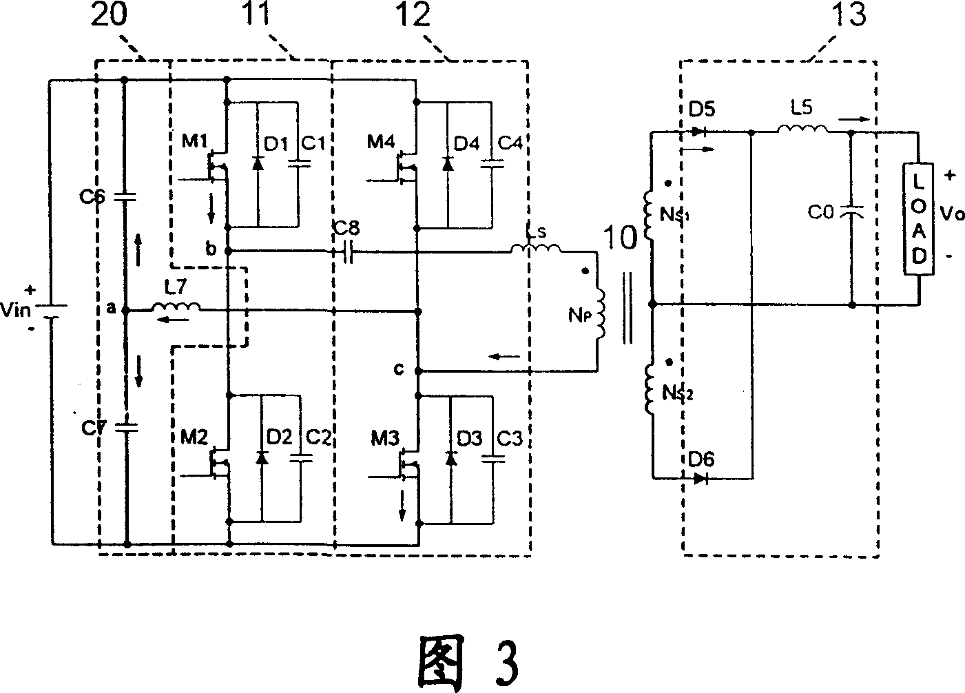
[0088] As shown in Figure 14, it is the third preferred embodiment of the present invention, its basic structure is still the same as that of the first embodiment, the difference is that the auxiliary bridge arm 20 is only composed of a single capacitor C7 and an inductor L7, due to the auxiliary The capacitance value of the bridge arm 20 is relatively large (referring to the capacitance values ​​of capacitors C6 and C7), which can ensure that ...


PUM


Abstract

The disclosed phase-shift full bridge circuit for flexible switch comprises: a transformer, a lead/lag bridge arm connected with one/another end of the primary side of transformer, an auxiliary bridge arm connected with power end, a break capacitor between primary side of transformer and the lead arm, and an output circuit set on secondary side of the transformer. This invention makes both the lead and lag arm fit to zero voltage switch, and turns off the rectifying diode with zero voltage.

Description

technical field [0001] The invention relates to a soft-switched phase-shifting full-bridge circuit, in particular to a soft-switching that enables both the leading bridge arm and the lagging bridge arm to easily realize zero-voltage switching, and effectively solves the reverse recovery problem of the output rectifier diode phase-shifted full-bridge circuit. Background technique [0002] Please refer to shown in Figure 19, it is a kind of existing phase-shifting type full-bridge circuit, and it comprises: a transformer 70; A leading bridge arm 71 is made up of two transistors M1, M2, and these two transistors M1, The connection node of M2 is connected to one end of the primary side of the transformer 70; a lagging bridge arm 72 is composed of two transistors M3 and M4, and the connection node of the two transistors M3 and M4 is connected to the other end of the primary side of the transformer 70 A resonant inductance Ls is connected in series between the connection nodes of...

Claims


Application Information

Patent Timeline
Patent Type & Authority Applications(China)
IPC IPC(8): H02M3/28H02M3/335H02M7/5387
CPCY02B70/1491Y02B70/10
Inventor 马小林周军马皓
Owner ACBEL POLYTECH INC
Why Eureka
Try Eureka