
Mounting device for a sputter source

A sputtering source and sputtering technology, applied in sputtering plating, ion implantation plating, coating, etc., can solve problems such as damage and target heat

Inactive Publication Date: 2007-11-07
SULZER METRO AG
View PDF3 Cites 0 Cited by
  • Summary
  • Abstract
  • Description
  • Claims
  • Application Information

AI Technical Summary

Problems solved by technology

Target becomes too hot and thus damaged

Method used


Image

  • Mounting device for a sputter source
  • Mounting device for a sputter source
  • Mounting device for a sputter source

Examples


Embodiment Construction

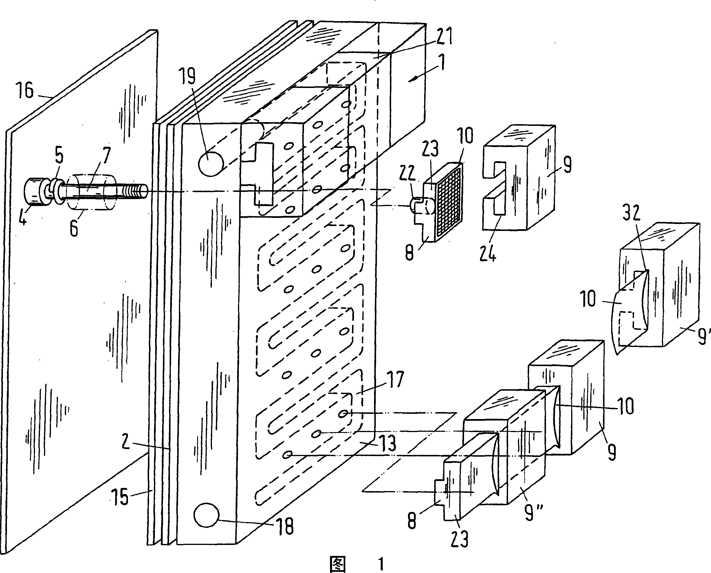
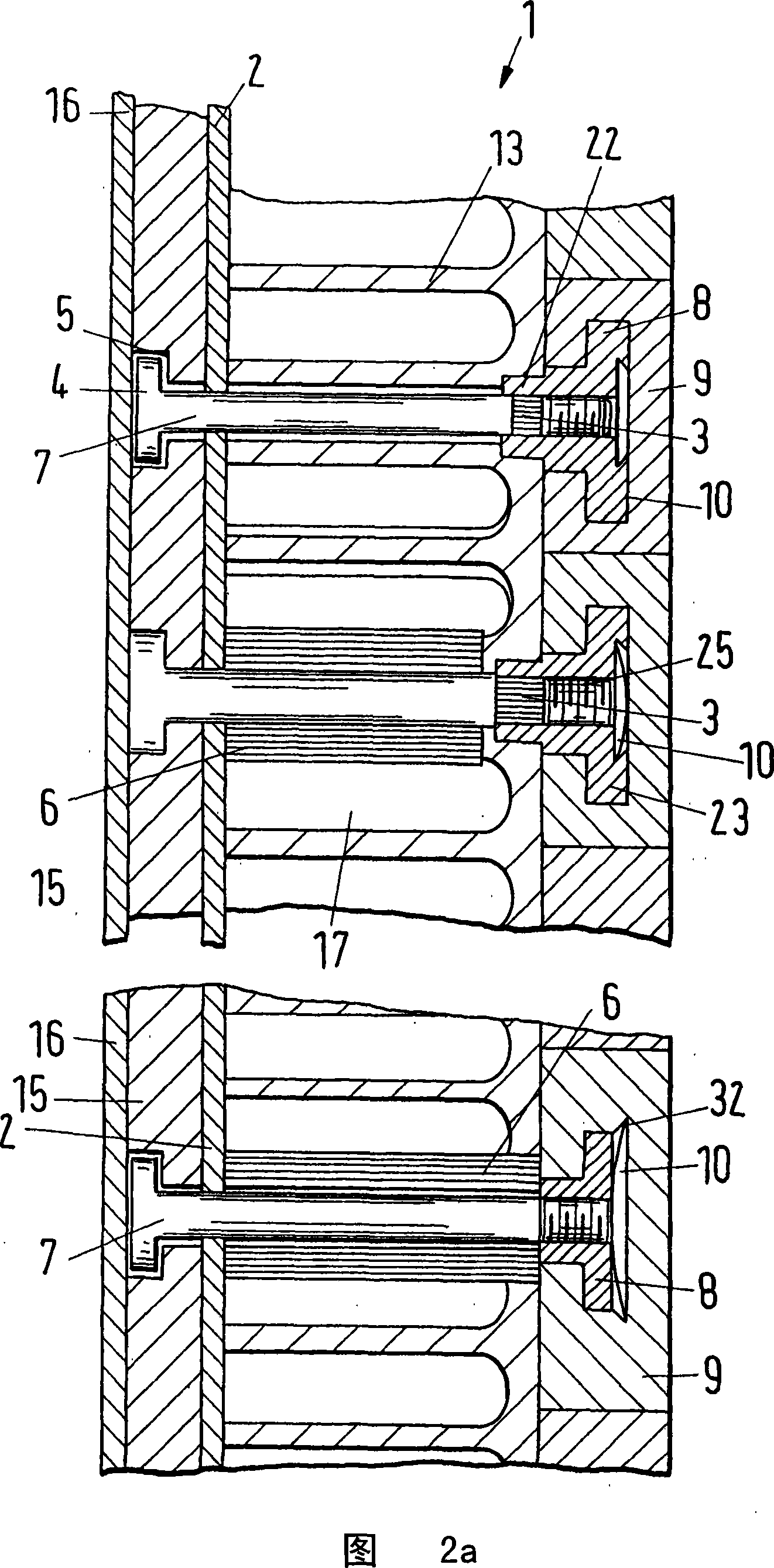
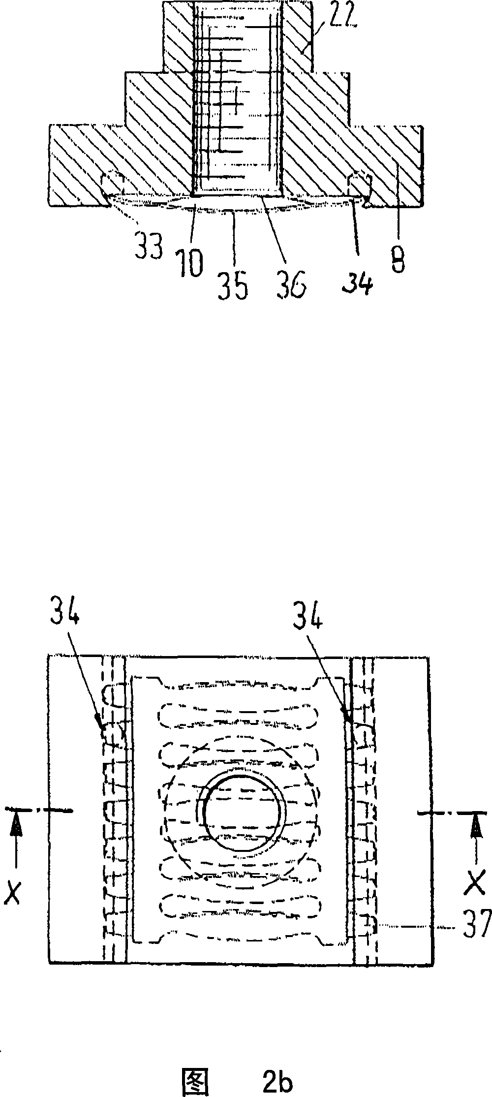
[0041] Figure 1 shows the arrangement of target segments 9 fastened to a target holder 1 in a coating source. Each target segment 9 is screwed to the outer wall 2 of the cooling body by means of a T-nut 8 . The T-nut comprises a cylindrical body 22 and an additional part 23 having a T-shaped cross-section. The cylinder 22 is received by a hole in the cooling body 13 . The T-shaped additional portion 23 protrudes beyond the inside surface of the cooling body. A contact layer 10 made of low-alloy copper or nickel, in particular CuBe, CuCoBe or NiBe, is attached to the T-nut and / or a galvanic coating is applied. At least one target segment 9 is plugged onto the T-nut 8 , and the T-nut and the target segment have an intermediate space in which the contact lamination 10 is arranged. In FIG. 1 the target segment 9 is plugged onto the T-shaped additional part 23 . A groove 24 is provided in the target section, said groove being widened into a T-shape, said groove being designed t...


PUM

PropertyMeasurementUnit
widthaaaaaaaaaa

Abstract

A target for a sputtering source can be subdivided into a plurality of exchangeable target segments ( 9 ). Each target segment ( 9 ) contains coating material, wherein each target segment ( 9 ) borders on at least two adjacent target segments ( 9', 9 ''), wherein each target segment is connectable to a base body ( 2, 13, 15 ) by means of at most one securing means ( 7, 8, 10 ).

Description

technical field [0001] The invention relates to a target and to an associated target holder for use in a coating method. The coating method includes in particular a gas sputtering method for applying a high-temperature-resistant adhesive layer to a substrate, for example, in particular to a turbine blade. The target contains a coating material which can be sputtered from the target, in particular by ions of an ionized noble gas plasma. The target is received on a target holder in the housing of the coating source. The coating material sputtered from the target reaches the substrate to be coated by means of a flow of ionized inert gas plasma. The coating source is located in a closed vacuum chamber to which a vacuum is continuously drawn. The deposited coating particles of the ionized inert gas and target reach the substrate inside the chamber or are pumped out by a vacuum pump. The target is welded to the target holder or screwed directly onto the target holder. One possi...

Claims


Application Information

Patent Timeline
Patent Type & Authority Applications(China)
IPC IPC(8): C23C14/34C23C14/54
CPCH01J37/3423H01J37/3497C23C14/3407H01J37/34H01J37/3435
Inventor W·比尔G·埃申多尔夫
Owner SULZER METRO AG
Learn More