Rotary electro magnetic electric energy quality comprehensive control device

A power quality and comprehensive control technology, applied in harmonic reduction devices, AC networks to reduce harmonics/ripples, reactive power compensation, etc., can solve problems such as low device overload capacity, lower device reliability, and increase device cost , to achieve the effect of low cost, suppression of harmonics, suppression and isolation of harmonics

Inactive Publication Date: 2007-11-14
HARBIN INST OF TECH
View PDF0 Cites 0 Cited by
  • Summary
  • Abstract
  • Description
  • Claims
  • Application Information

AI Technical Summary

Problems solved by technology

[0005] The purpose of the present invention is to provide a rotating electromagnetic type power quality comprehensive control device, to overcome the power quality control device of the prior art because of the use of power semiconductor devices, on the one hand, the cost of the device is increased, and on the other hand, the reliability of the device is reduced. , and the overload capacity of the device is low, which will generate new harmonic interference defects

Method used


Image

  • Rotary electro magnetic electric energy quality comprehensive control device
  • Rotary electro magnetic electric energy quality comprehensive control device

Examples


specific Embodiment approach 1

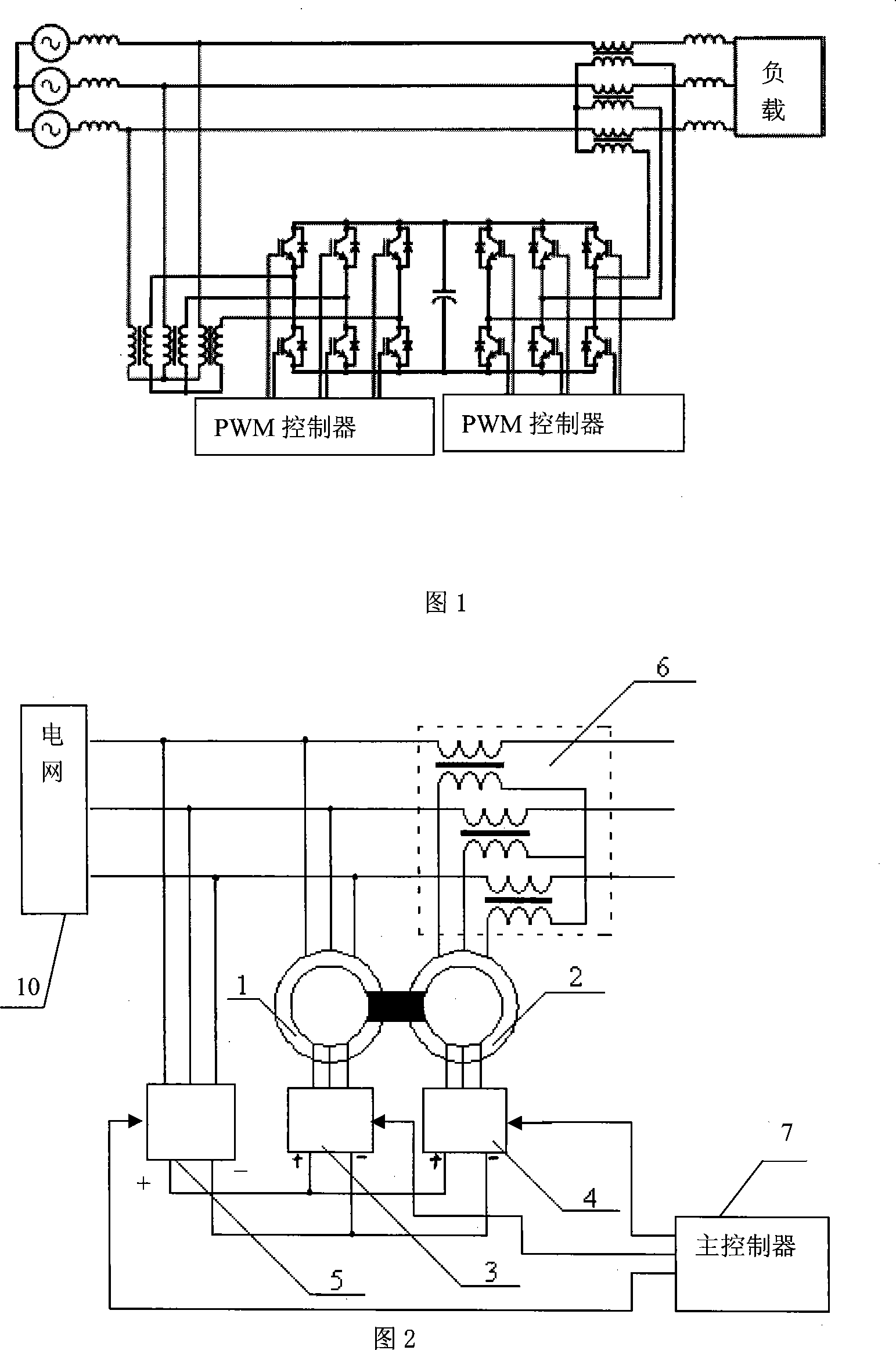
[0009] Specific implementation mode 1: This implementation mode will be specifically described below with reference to FIG. 2 . This embodiment is composed of No. 1 wound rotor induction motor 1, No. 2 wound rotor induction motor 2, No. 1 inverter 3, No. 2 inverter 4, rectifier 5, transformer 6 and main controller 7, The positive output terminal of the rectifier 5 is connected to the positive input terminals of the No. 1 inverter 3 and the No. 2 inverter 4, and the negative output terminal of the rectifier 5 is connected to the negative input terminals of the No. 1 inverter 3 and the No. 2 inverter 4. The three-phase output end of the No. 1 inverter 3 is connected to the three-phase rotor winding of the No. 1 wound rotor induction motor 1, and the three-phase output end of the No. 2 inverter 4 is connected to the No. 2 wound rotor induction motor 2. On the three-phase rotor winding, the rotor of No. 1 wound rotor induction motor 1 and the rotor of No. 2 wound rotor induction m...

specific Embodiment approach 2

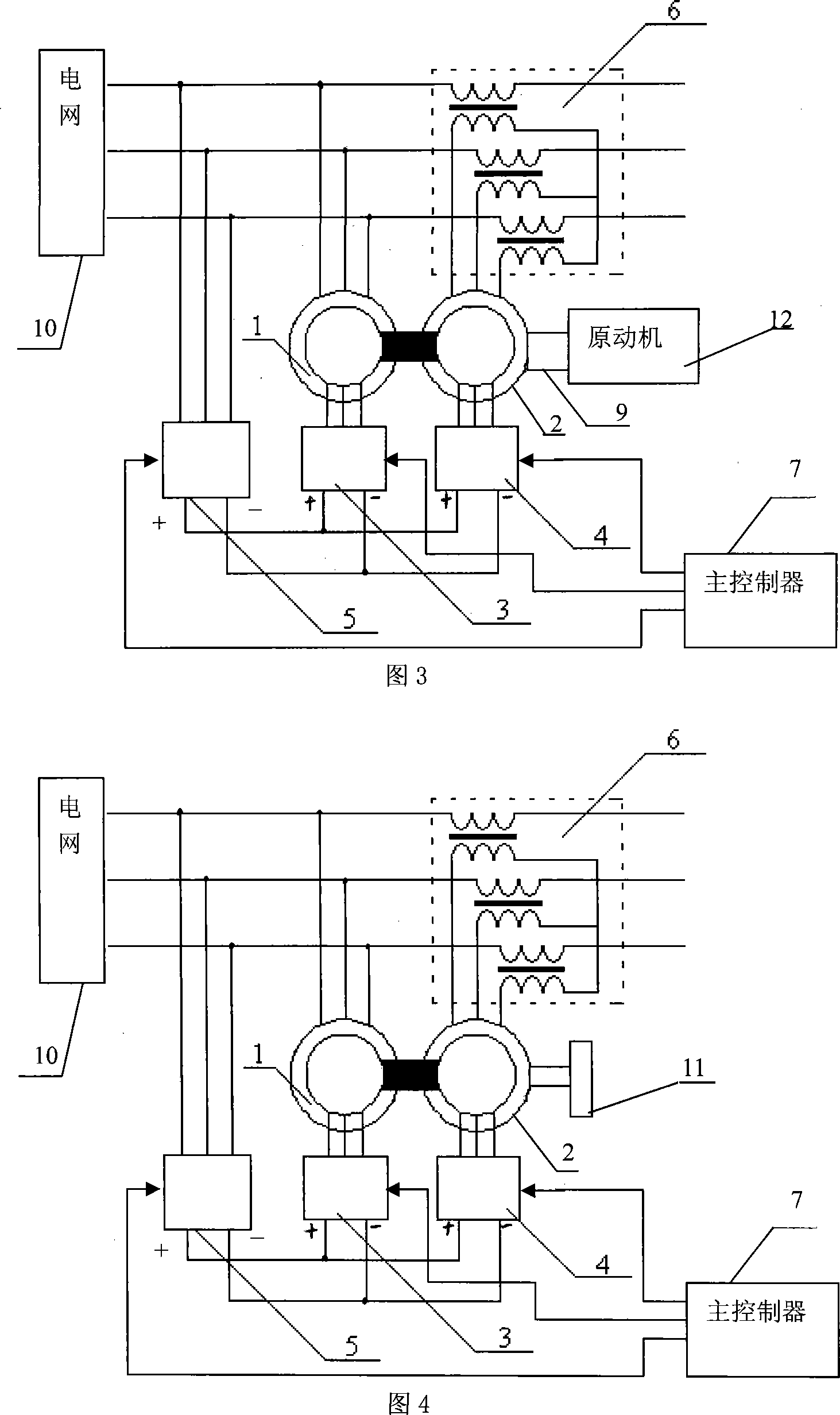
[0013] Specific Embodiment 2: The present embodiment will be specifically described below with reference to FIG. 3 . The difference between this embodiment and Embodiment 1 is that it also includes a clutch 9 and a prime mover 12. The engine shaft of the prime mover 12 is fixed to the No. 1 wound rotor induction motor 1 or the No. 2 wound rotor induction motor through the clutch 9. The rotor shaft end of the motor 2 to realize coaxial rotation. When the power grid and the load need to continuously compensate active power, the rotating electromagnetic power quality comprehensive control device operates in the generator mode, and can use the prime mover to drive the rotor of the induction motor. By controlling the magnitude and frequency of the output current of the No. 1 inverter 3, Even if the speed of the prime mover changes, it can output active power with a constant frequency to the grid and loads to achieve uninterrupted power supply, or use wind energy, water energy and o...

specific Embodiment approach 3

[0014] Embodiment 3: The difference between this embodiment and Embodiment 2 is that the prime mover can be a power device such as a gas engine, a wind engine, or a water turbine engine. Other composition and connection methods are the same as those in Embodiment 2.


PUM


Abstract

The invention is a rotary electromagnetic electric energy quality synthetic control device, belonging to the field of electric machine and power electronics technique, and it comprises winding rotator induction electric machines 1 and 2, inverters 1 and 2, rectifier, transformer and master controller, where the output end of the rectifier is connected with those of the inverters and the output end of the first inverter is connected with the rotator winding of the first winding rotor induction electric machine and the output end of the second inverter is connected with the rotator winding of the second induction electric machine, and the rotors of the two induction electric machines are fixed and coaxially rotate, the stator winding of the second induction electric machine is connected with the primary side of the transformer and the controlled ends of the two inverters and the rectifier are separately connected with the output ends of the master controller.

Description

technical field [0001] The invention relates to a power quality control device, which belongs to the technical field of motors and power electronics. Background technique [0002] With the increasingly widespread application of power electronic devices, the harmonic pollution in the power grid is also becoming more and more serious. In addition, the power factor of many power electronic devices is very low, which also brings additional burden to the grid and affects the quality of power supply. Therefore, eliminating harmonic pollution and improving power factor has become a major issue in power electronics technology. [0003] Typical devices used to compensate reactive power include static var compensators and static var generators. Typical devices used to compensate harmonics are power active filters. A typical device used for power system power flow control is the unified power flow controller. The main structure of the unified power flow controller is shown in Figure...

Claims


Application Information

Patent Timeline
Patent Type & Authority Applications(China)
IPC IPC(8): H02J3/18H02J3/01
CPCY02E40/30Y02E40/40
Inventor 寇宝泉谢大纲李立毅
Owner HARBIN INST OF TECH
Why Eureka
Try Eureka