Non-contact thermal shock high-temperature mechanical test device

A high-temperature mechanics and testing device technology, applied in measurement devices, using repetitive force/pulse force to test material strength, and using stable tension/pressure to test material strength, etc., can solve the problem of poor interchangeability and adaptability of induction components, Difficulty in material selection and design, difficulty in multi-angle real-time observation, etc., to reduce power consumption and cooling difficulty, increase test flexibility, and reduce mutual interference

Pending Publication Date: 2020-02-25
NANJING UNIV OF AERONAUTICS & ASTRONAUTICS
View PDF3 Cites 6 Cited by
  • Summary
  • Abstract
  • Description
  • Claims
  • Application Information

AI Technical Summary

Problems solved by technology

[0004] Comprehensive analysis of the above-mentioned devices, the above existing detection devices have the following deficiencies: 1) the above-mentioned devices are heated by resistance furnaces, graphite furnaces, etc., the heating area is large, and the power consumption is high, and the experimental fixture is arranged in the high-temperature zone, so material selection and design are difficult ;Using high-temperature induction furnace heating can only heat high-conductivity samples, and the interchangeability and adaptability of induction parts are poor, so it is not suitable for application on some specimens and composite materials with complex shapes; 2) It is difficult to carry out simultaneous mechanical testing Test experiments such as thermal shock, thermal fatigue, and laser damage; 3) For experiments such as fracture, only incisions and prefabricated cracks can only be pre-processed, and local controllable damage cannot be introduced into the test; 4) The cavity of the heating part is large and sealed, so that the observation window Small, difficult to achieve multi-angle real-time observation

Method used


Image

  • Non-contact thermal shock high-temperature mechanical test device
  • Non-contact thermal shock high-temperature mechanical test device
  • Non-contact thermal shock high-temperature mechanical test device

Examples


Embodiment 1

[0033] Embodiment 1 Focusing infrared lamp experiment

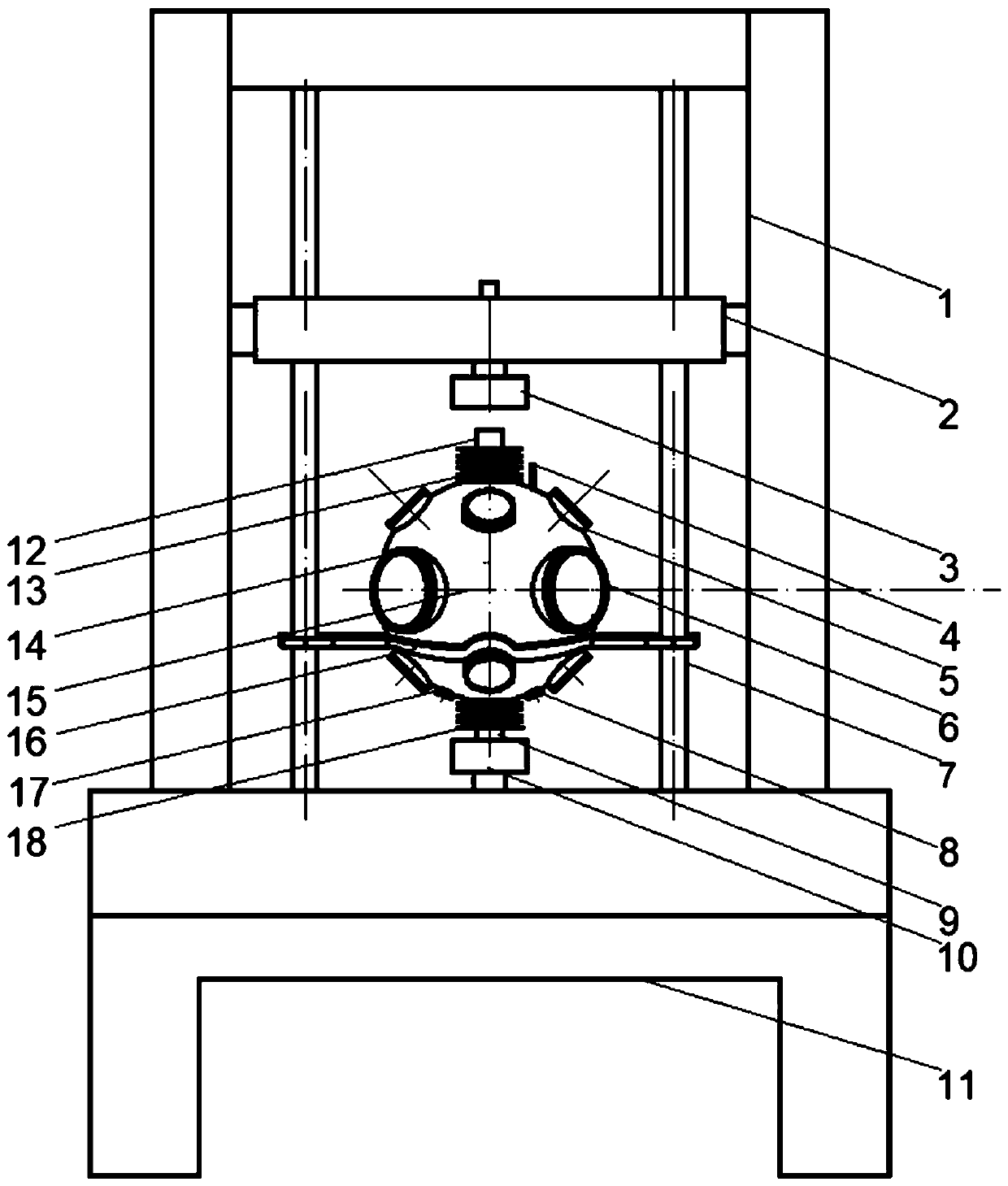
[0034] figure 1 It is a schematic diagram of the overall structure of a non-contact thermal shock high temperature mechanical testing device of the present invention. from figure 1 It can be seen that the non-contact thermal shock high-temperature mechanical testing device includes a base 11 and a mechanical experiment module 1 fixed on the base 11. A cavity is formed between the mechanical test module 1 and the base 11, and a middle beam 2 is arranged horizontally in the cavity. , both ends of the middle beam 2 are fixedly connected with the mechanical test module; two symmetrical guide rails 7 are longitudinally arranged in the cavity, one end of the guide rail 7 is fixedly connected with the mechanical test module, and the other end is fixedly connected with the base 11; the middle beam 2 The lower part of the cavity is fixed with an upper clamp 3 outside the cavity, and the upper surface of the base 11 is correspond...

Embodiment 2

[0051] Embodiment 2 laser experiment

[0052] The difference between this embodiment and embodiment 1 lies in the experimental environment and heating method. After the spherical cavity 15 is vacuumized, open the intake module 17 with a flowmeter, and fill the spherical cavity 15 with argon until the air pressure reaches 10 -2 pa.

[0053] Do not use infrared lamp heating module, only use laser heating module. Turn on the laser heating module 6 , adjust the optical path of the laser in the visible light mode, and adjust the focal length of the laser in the low power state to focus on the test area of ​​the specimen 21 . The laser drive power is remotely controlled by the computer. In the continuous output mode, the laser output power is gradually increased to 600W. At the same time, the temperature of the test piece is monitored by the infrared temperature measuring device 23 and the colorimeter. After reaching 1600°C, the laser maintains the temperature in pulse mode and P...

Embodiment 3

[0055] Embodiment 3 infrared-laser synchronous heating experiment

[0056] The experimental device of this embodiment is the same as that of Embodiment 1, except that the infrared module 5 and the laser module 6 are used simultaneously to heat the test piece 21 in the experimental steps.

[0057] Start the infrared lamp heating module 5, and adjust the focal lengths of the four infrared lamps in a low power state to focus on the test piece 21. Then the laser heating module 6 is turned on, the optical path of the laser is adjusted in the visible light mode, and the focal length of the laser is adjusted in the low power state to focus on the test piece 21 . Afterwards, the infrared module is controlled to heat the sample surface to a constant temperature of 800°C. Then turn on the laser module, gradually increase the output power, and use the infrared temperature measurement and colorimeter feedback to make the temperature of the sample area reach an ultra-high temperature stat...


PUM


Abstract

The invention discloses a non-contact thermal shock high-temperature mechanical test device, and belongs to the field of high-temperature mechanical performance test. The device comprises a base, a mechanical test module, a middle cross beam, an out-cavity upper clamp and a spherical cavity, wherein the spherical cavity is fixed on a guiderail through a cavity bracket; an upper pull rod, an uppervacuum corrugated pipe, a vacuum gauge, an infrared lamp heating module, a laser heating module, a sample injection door with an observation window, an infrared temperature measurement module, a dynamic test module, a vacuum air exhaust module, an air intake module, a lower pull rod and a lower vacuum corrugated pipe are arranged on the spherical cavity; and an extensometer, an in-cavity upper clamp, an in-cavity lower clamp and a test piece are arranged in the spherical cavity. The device is capable of providing freely switched thermal load environment, vacuum or inert gas environment and laser thermal shock environment, is convenient to mount / dismount, has high flexibility and sealing property, and is capable of realizing dynamic and multi-angle observation.

Description

technical field [0001] The invention belongs to the field of experimental equipment for high-temperature materials, and specifically relates to a non-contact thermal shock high-temperature mechanical testing device, which can realize testing environments such as laser shock, high temperature, vacuum, and inert gas. Background technique [0002] With the development of strategic technologies such as hypersonic spacecraft and high thrust-to-weight ratio engines, the study of mechanical problems of material structures in extreme high-temperature environments (especially high-temperature oxidation environments above 2000 °C) has raised a series of challenging problems that need to be urgently solved. The high-temperature three-dimensional stress state, micro-nano structure evolution, and dynamic behavior of the atom-electronic system of materials under extreme high-temperature conditions all have a crucial impact on the service performance of the structure and the damage resistan...

Claims


Application Information

Patent Timeline
Patent Type & Authority Applications(China)
IPC IPC(8): G01N3/60G01N3/18G01N3/32G01N3/04G01N1/28G01N17/00
CPCG01N1/286G01N3/04G01N3/18G01N3/32G01N3/60G01N17/004G01N2001/2886G01N2203/0226G01N2203/0236G01N2203/0423
Inventor 周建新胡俊斌郭万林王辽宇
Owner NANJING UNIV OF AERONAUTICS & ASTRONAUTICS
Why Eureka
Try Eureka