Multi-phase current supplying circuit, driving apparatus, compressor, and air conditioner

一种多相电流、电路的技术,应用在电路装置、用于限制过电流/过电压的紧急保护电路装置、控制机电传动装置等方向,能够解决逆变器电路4损伤大等问题,达到降低充电速度、抑制高次谐波、减小的值的效果

Active Publication Date: 2007-11-14
DAIKIN IND LTD
View PDF0 Cites 13 Cited by
  • Summary
  • Abstract
  • Description
  • Claims
  • Application Information

AI Technical Summary

Problems solved by technology

Therefore, as shown in Figure 15, at the AC voltage V in When the lightning surge is superimposed, even if the value is reduced by the lightning arrester 7, the possibility of large damage to the inverter circuit 4 is still high

Method used


Image

  • Multi-phase current supplying circuit, driving apparatus, compressor, and air conditioner
  • Multi-phase current supplying circuit, driving apparatus, compressor, and air conditioner
  • Multi-phase current supplying circuit, driving apparatus, compressor, and air conditioner

Examples


no. 1 Embodiment approach

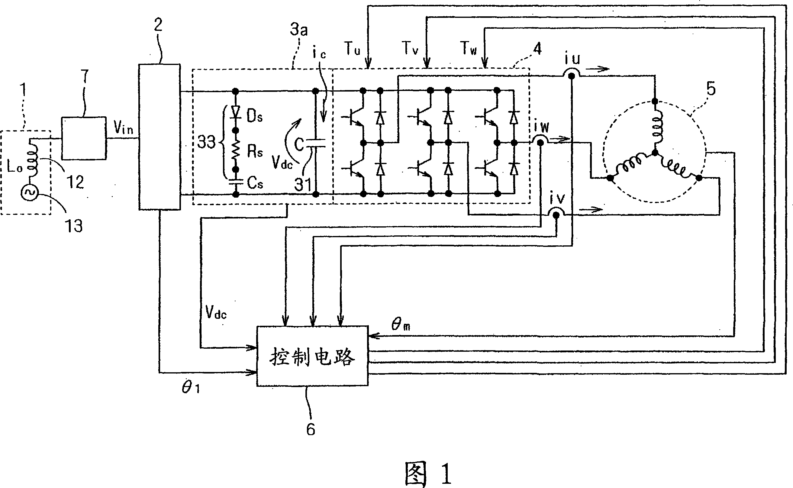
[0062] FIG. 1 is a circuit diagram showing a drive device according to a first embodiment of the present invention. This drive device has a motor 5 as a drive unit, and a multi-phase current supply circuit that supplies multi-phase current to the motor 5 .

[0063] The multiphase current supply circuit has a converter 2 , an intermediate circuit 3 a , an inverter 4 , a control circuit 6 and a lightning arrester 7 . The converter 2 is connected to the single-phase or three-phase multi-phase power supply system 1 through the arrester 7, and the AC voltage V in be rectified. However, as described above, there is parasitic inductance in the power supply system 1 , so the inductor 12 connected in series with the AC power supply 13 represents the parasitic inductance. Here, the value L of the parasitic inductance of each phase 0 Use 230μH.

[0064] Converter 2 rectifies the AC voltage V in And input to the intermediate circuit 3a. The intermediate circuit 3 a has a capacitor 3...

no. 2 Embodiment approach

[0093] Fig. 8 is a circuit diagram showing an intermediate circuit 3b used in the drive device according to the second embodiment of the present invention. The intermediate circuit 3 b is configured to further include an inductor 32 relative to the intermediate circuit 3 a. Specifically, the inductor 32 is connected in series with respect to the parallel connection of the capacitor 31 and the bypass 33 . By using the intermediate circuit 3b as the intermediate circuit 3 shown in FIG. 1 , not only does the bypass 33 function, but the inductor 32 moderates the rising slope of the current flowing in the parallel connection of the capacitor 31 and the bypass 33 . Therefore, the rectified voltage v when a lightning surge occurs can be more effectively suppressed dc voltage rises.

[0094] Fig. 9 shows the AC voltage V when using the intermediate circuit 3b in Waveform 101, capacitor C S Waveform 105 of the voltage at both ends of the rectified voltage v dc The graph of wavefor...

no. 3 Embodiment approach

[0099] 10 is a circuit diagram showing part of a multiphase current supply circuit according to a third embodiment of the present invention. Here, the diode bridge 2, the inverter 4 and the lightning arrester 7 are omitted, but the structure is the same as that shown in FIG. 1 . In addition, in this embodiment, an intermediate circuit 3 d is used instead of the intermediate circuit 3 a of FIG. 1 .

[0100] The intermediate circuit 3 d is configured by adding the bypass 34 connected in parallel to the capacitor 31 to the intermediate circuit 3 a described using FIG. 1 in the first embodiment. Bypass 34 has switching elements namely transistor Q and resistor R B series connection.

[0101] The control circuit 6 according to the rectified voltage v dc , to provide the bias voltage CNQ to the base of the transistor Q. at rectified voltage v dc When the first specified value is exceeded, the transistor Q is turned on, and the rectified voltage v dc When it is lower than the s...


PUM


Abstract

A multi-phase current supplying circuit comprises a converter (2), an intervening circuit (3a), an inverter (4), a control circuit (6) and a lightning arrester (7). A power supply system (1) is connected to the converter (2) via the lightning arrester (7), whereby an AC voltage (Vin) is rectified. The intervening circuit (3a) has a capacitor (31) and a shunt (33) connected in parallel thereto. The shunt (33) comprises a series connection of a diode (DS), a resistor (RS) and a capacitor (CS), and a direction extending from the anode of the diode (DS) toward the cathode thereof is coincident with a direction extending from the higher potential side of a smoothing capacitor toward the lower potential side thereof.

Description

technical field [0001] The present invention relates to inverter technology. Background technique [0002] FIG. 11 is a circuit diagram showing the configuration of a conventional multiphase current supply circuit. The power supply system 1 has a single-phase or three-phase multi-phase AC power supply 13, which provides an AC voltage V to an AC-DC converter (hereinafter referred to as "converter") 2 in . However, the inductance parasitic in the power supply system 1 is shown as an inductor 12 connected in series with an AC power supply 13 . [0003] An intermediate circuit 3 is provided between the converter 2 and the inverter 4 , and the output of the converter 2 is supplied to the intermediate circuit 3 . The intermediate circuit 3 has a capacitor 31 , and the output of the converter 2 is supplied to both ends of the capacitor 31 . The capacitance value C of the capacitor 31 is set small, for example, 20 μF. Capacitor 31 can be downsized by reducing the capacitance va...

Claims


Application Information

Patent Timeline
Patent Type & Authority Applications(China)
IPC IPC(8): H02M7/48H02P27/06H02P21/05H02P21/22H02P23/04H02P25/026H02P27/08
CPCH02M5/458H02H7/1222H02H9/04
Inventor 山井広之关本守满
Owner DAIKIN IND LTD
Why Eureka
Try Eureka