Frequency optical-mode matrix inputting module
An input module and matrix technology, applied in the field of optical splitter photoelectric switch circuit, can solve the problems of complex structure, huge circuit, high production cost, etc., and achieve the effect of compact and simple circuit structure, easy to organize mass production, and low production cost
- Summary
- Abstract
- Description
- Claims
- Application Information
AI Technical Summary
Problems solved by technology
Method used
Image
Examples
Embodiment 1
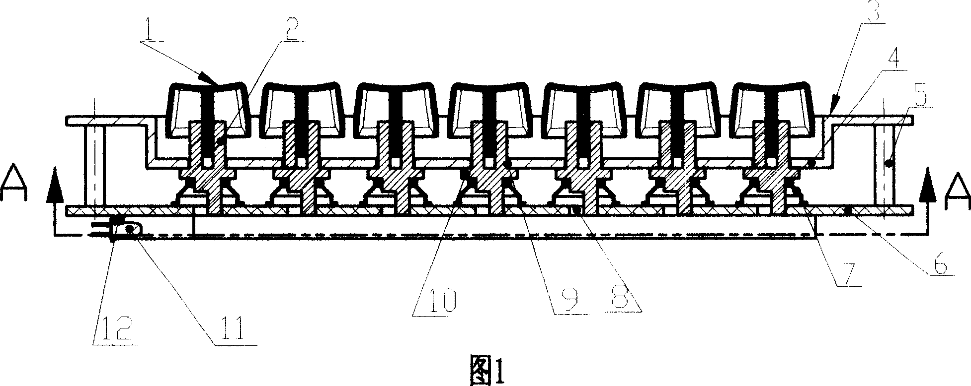
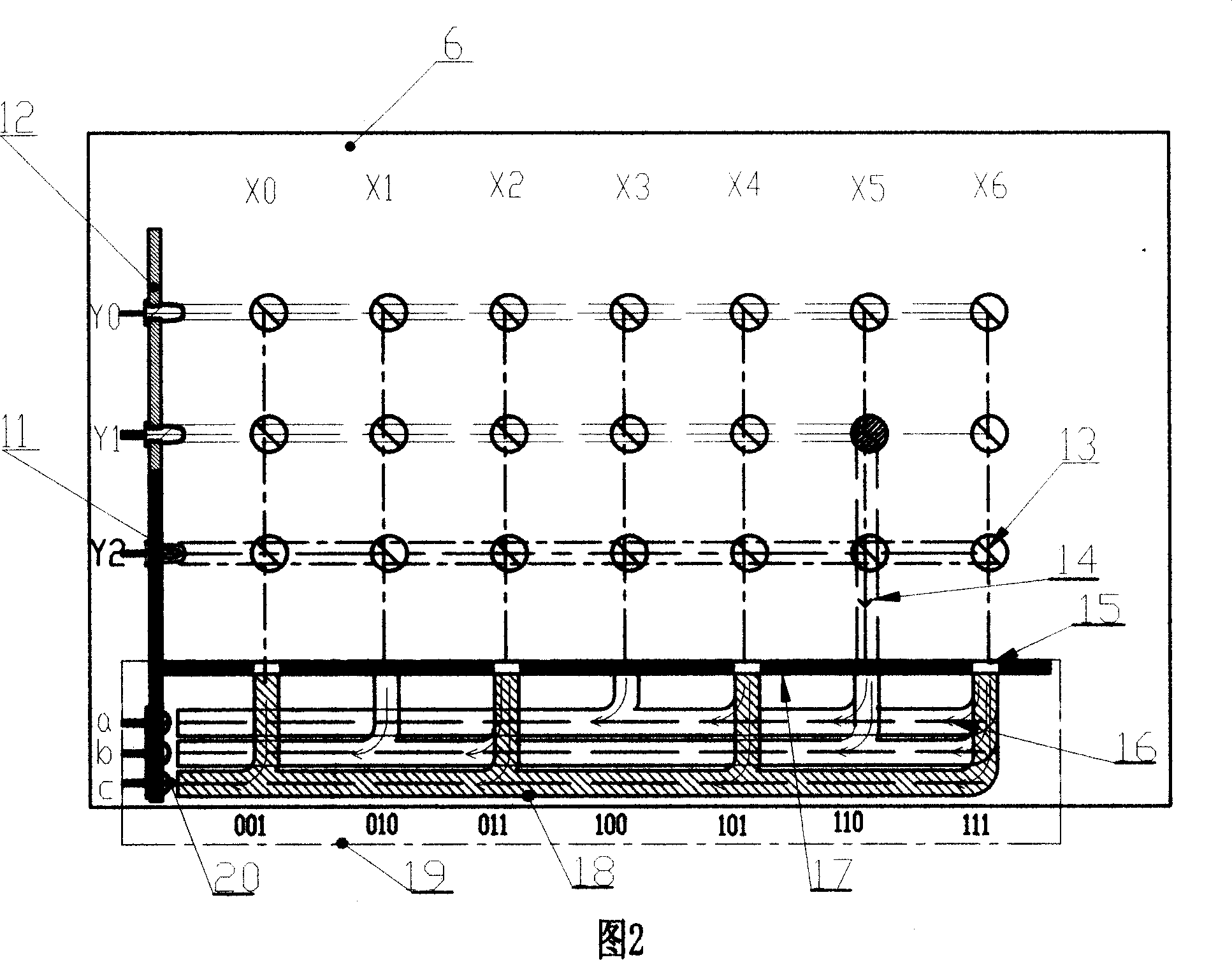
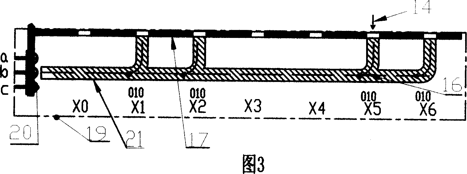
[0030] Referring to Fig. 1, 2, the present invention is made of horizontally arranged keys, transmitter 11, elastic body 7, housing, key reflective surface 13, optical encoder 19, photoelectric input circuit controller (not shown in the figure) and the like.
[0031] Referring to Fig. 1, the panel 3 is in the shape of a flat plate with a concave middle part, and there are panel through-holes 9 arranged horizontally on the square concave bottom surface 4 in the middle. 5 are connected to form a hollow housing with parallel board surfaces. On the lower surface near the left part of the bottom plate 6, there are left vertical boards 12 respectively equipped with transmitters 11 and receivers 20.
[0032] Referring to Fig. 1, the upper part of the key cap 1 and the key guide 2 is fixedly connected to form a button, the bottom surface of the elastic body 7 is connected with the upper surface of the bottom plate 6, and its upper part is connected with the bottom surface of the should...
Embodiment 2
[0051] Referring to Fig. 6, an optical fiber receiving tube 24 is installed on the left vertical plate 12 top, the optical input end of the optical fiber 25 is positioned at the right side of the base plate 6 and corresponds to the transmitter 11, and the optical output end of the optical fiber 25 is respectively connected to e, f, g optical fiber receiving Tube 24 corresponds.
[0052] The distribution and arrangement of the optical fiber 25 can adopt the arrangement in Figure 6; when the number of rows Y is more, the arrangement of the beam splitter 18 in Embodiment 1 can also be adopted,
[0053] Referring to Fig. 12, the receiving tube 20 in this figure is an optical fiber receiving tube 24, and the photoelectric conversion circuit 33 containing the optical fiber receiving tube 24 is electrically connected with the input circuit controller (not shown in the figure).
[0054] When the key is not pressed, the several key reflective surfaces 13 arranged vertically and horizon...
Embodiment 3
[0057] Referring to Fig. 7, the optical splitter 18 is corresponding to the key reflection surface 13 respectively by its light input end according to a certain arrangement; The key reflective surface 13 and the photoelectric conversion circuit 33 including the receiver 20 constitute. When the keyed reflected light 14 is incident on the light input end of the optical fiber 26 , the split optical path 16 is formed on the inner surface of the optical fiber 26 .
[0058] One end of one or more optical fibers 26 runs through the surface of the vertical plate 17 and corresponds to the key reflective surface 13 of each row; the other end of the optical fiber 26 corresponds to the receiver 20 after being fixed. The corresponding relationship between the key reflective surface 13 and the receiver 20 is as follows
[0059] X0 key reflection surface 13--optical fiber 26--a receiver 20
[0060] X1 key reflection surface 13--optical fiber 26-b receiver 20
[0061] X2 key reflection sur...
PUM
 Abstract
Description
Claims
Application Information
 - R&D Engineer
- R&D Manager
- IP Professional
- Industry Leading Data Capabilities
- Powerful AI technology
- Patent DNA Extraction
Browse by: Latest US Patents, China's latest patents, Technical Efficacy Thesaurus, Application Domain, Technology Topic, Popular Technical Reports.
© 2024 PatSnap. All rights reserved.Legal|Privacy policy|Modern Slavery Act Transparency Statement|Sitemap|About US| Contact US: help@patsnap.com


