Digital control lathes

A technology for CNC lathes and CNC machine tools, which is applied in the field of CNC lathes to achieve the effects of stable machine tool accuracy, large processing area space, and stable accuracy

Active Publication Date: 2007-11-28
浙江海德曼智能装备股份有限公司
View PDF1 Cites 6 Cited by
  • Summary
  • Abstract
  • Description
  • Claims
  • Application Information

AI Technical Summary

Problems solved by technology

[0003] The purpose of the present invention is to solve the above-mentioned problems existing in the existing CNC lathes, and to provide a better isolation and protection between the machining position and the sliding parts in the X-axis direction and the Z-axis direction, with a large processing area, easy cleaning of chips, and the ability to process complex workpieces CNC lathe

Method used


Image

  • Digital control lathes
  • Digital control lathes
  • Digital control lathes

Examples


Embodiment Construction

[0028] The following are specific embodiments of the present invention and in conjunction with the accompanying drawings, the technical solutions of the present invention are further described, but the present invention is not limited to these embodiments.

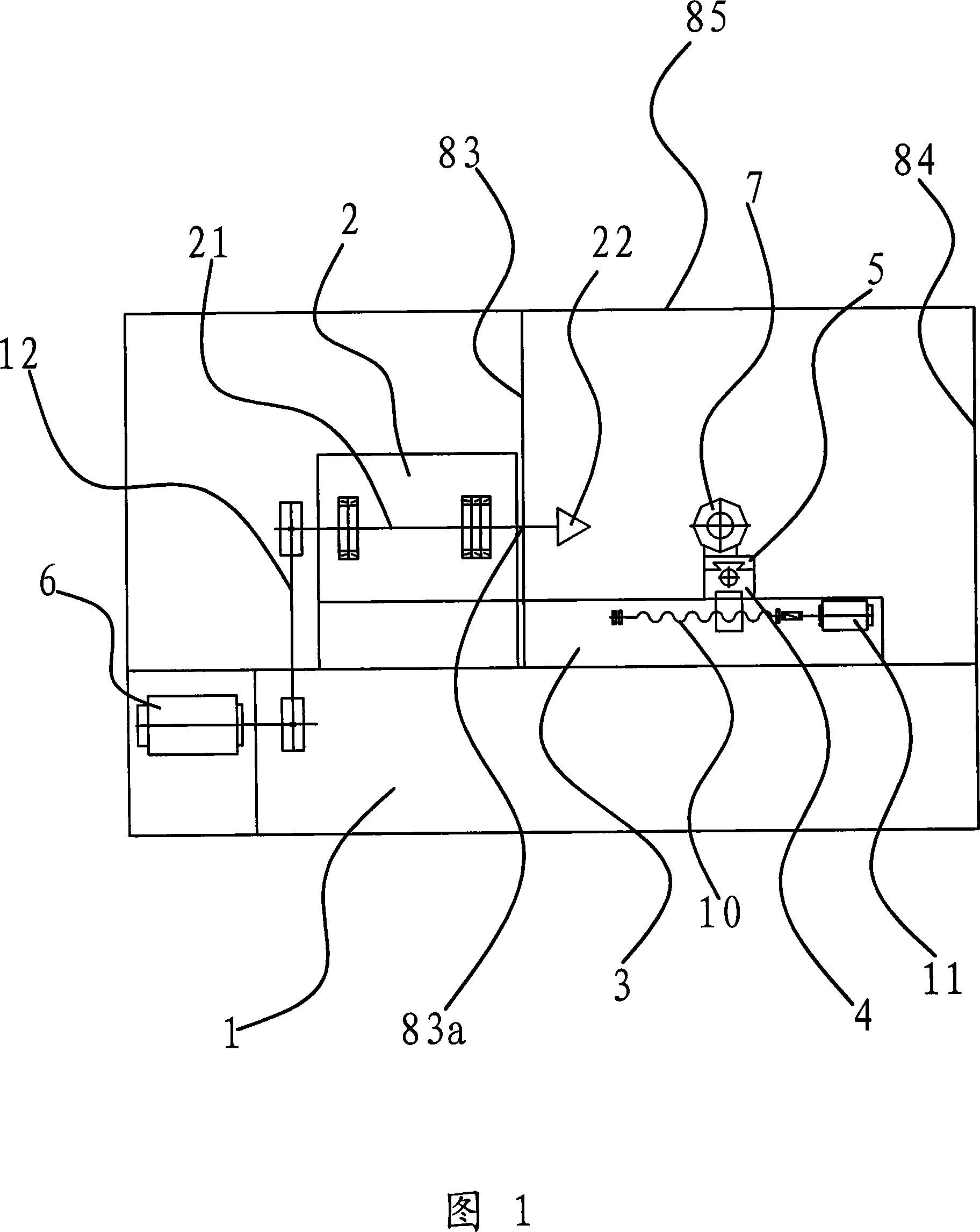
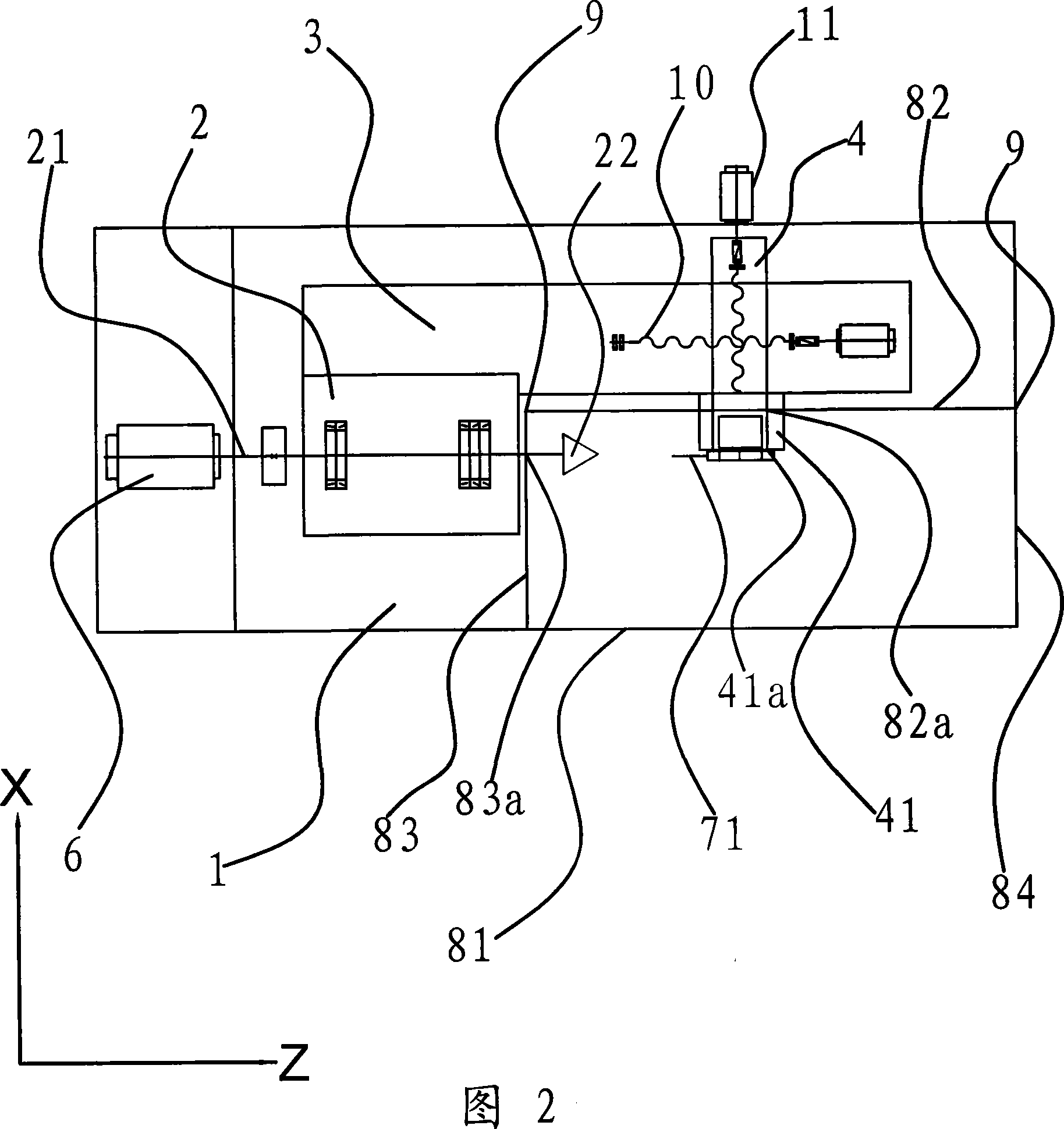
[0029] As shown in Figures 1 and 2, the CNC lathe includes a lathe base 1 and a bed 3 and a spindle box 2 located on the top of the lathe base 1. The main shaft 21 of the lathe runs through the spindle box 2, and one end of the lathe is connected to the motor 6 through a belt 12. connection, the other end is provided with a chuck 22, on the above-mentioned bed, there is a lower slide 5 that can slide along the X-axis direction, and on the lower slide 5, there is an upper slide 4 that can slide along the Z-axis. 4 is fixed with a tool holder 7, which is characterized in that the main shaft 21 and the lower slide plate 5 are in a misaligned position in the Z direction, and a tool holder 22 and the tool holder 7 are provided a...


PUM


Abstract

The present invention provides one kind of numerically controlled lathe without contamination of drive components caused by cutting scrap. The numerically controlled lathe includes a pedestal, a lathe bed, a headstock, a spindle connected to motor and chuck, a lower slide carriage, an upper slide carriage, a cutter head, and protecting cover to cover the chuck and the cutter head. The present invention has complete separation of the machining location from the X-axis, the Y-axis and the headstock, so that no cutting scrap and cutting fluid will contaminate the drive components and the control system and the lathe has stable precision.

Description

technical field [0001] The invention relates to a numerically controlled lathe, in particular to a numerically controlled lathe provided with a protective cover. Background technique [0002] A CNC lathe is a lathe that uses computer numerical control technology to control a servo motor to complete machining. Because can produce a lot of chip, dust etc. can seriously pollute lathe in the machining process, reduce the service life of lathe, so people are provided with protective cover on lathe, but there are many problems in the protection aspect of existing protective cover, as application number is The Chinese patent document of 200320103530.6 discloses a numerically controlled lathe. One end of the bed of the lathe is provided with a head box, and a guide rail is provided on the bed. A movable saddle is provided on the guide rail. The saddle is driven by a longitudinal ball screw, and the saddle There is a slide plate that can move horizontally, the slide plate is driven ...

Claims


Application Information

Patent Timeline
Patent Type & Authority Applications(China)
IPC IPC(8): B23B7/00B23B7/10B23B25/04B23Q11/08
Inventor 高长泉
Owner 浙江海德曼智能装备股份有限公司
Why Eureka
Try Eureka