Clock switching circuit

A clock switching and circuit technology, applied in the direction of electrical components, pulse processing, signal generation/distribution, etc., can solve problems affecting circuit stability, clock signal has glitch distance, far and small, etc., to achieve the effect of eliminating glitches

Active Publication Date: 2007-11-28
SOUTHEAST UNIV
View PDF0 Cites 21 Cited by
  • Summary
  • Abstract
  • Description
  • Claims
  • Application Information

AI Technical Summary

Problems solved by technology

[0002] Although the ordinary data selector circuit can complete the switching of the input clock signal, due to the difference in the input clock frequency and the asynchrony of the selection control signal, it is easy to cause the clock signal to have glitches or adjacent transition edges during the switching process. The distance between is much less than half a period of the clock
This unstable clock switching process is prone to false trigger events and will affect the stability of the circuit

Method used


Image

  • Clock switching circuit
  • Clock switching circuit
  • Clock switching circuit

Examples


Embodiment Construction

[0015] The present invention will be further described in detail below in conjunction with the accompanying drawings and specific embodiments.

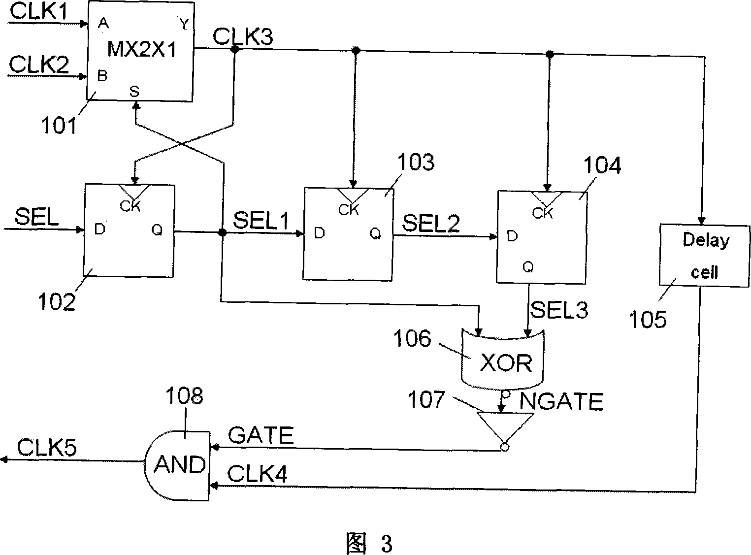
[0016] Figure 3 is a two-way clock switching circuit, in which the main components are: a data selector switching circuit 101, D-type flip-flops 102, 103 and 104, a delay unit circuit 105, an exclusive OR gate 106, a NOT gate 107 and AND gate 108. The main signals included are: two input clock signals CLK1 and CLK2, directly switch the clock signal output CLK3, clock selection signal SEL, and the SEL signal is synchronized with CLK3 by D flip-flops 102, 103, 104 in sequence to obtain trigger signals SEL1, SEL2, SEL3 , the NGATE signal obtained by XOR of SEL1 and SEL3 and its inverse signal GATE, the delayed clock signal CLK4 of CLK3, and the final output glitch-free clock signal CLK5.

[0017] The two clock inputs of the one-of-two data selector switching circuit 101 are CLK1 and CLK2 , and the output is a glitched clock signal CLK3 ...


PUM


Abstract

The invention discloses a clock commutation circuit without burr, which is characterized by the following: comprising data selector, multistage three grades synchronous circuit, time delay circuit and gate controlling circuit; switching the imputing clock signal with the data selector; generating the clock signal with burr; synchronizing the three grades synchronous circuit and the outputting signal of the data selector; excluding the outputting signal of the first grade synchronous circuit and the third synchronous circuit in the gate controlling circuit; masking the burr of clock signal switching; delaying time for the clock signal with the time delay circuit; avoiding simultaneous roll-over of the clock signal edge and the electrical level of the synchronous circuit outputting; generating new burr. This invention can be used to the system with multipath clock signal.

Description

technical field [0001] The invention relates to a clock switching circuit, in particular to a glitch-free clock switching circuit. Background technique [0002] Although the ordinary data selector circuit can complete the switching of the input clock signal, due to the difference in the input clock frequency and the asynchrony of the selection control signal, it is easy to cause the clock signal to have glitches or adjacent transition edges during the switching process. The distance between them is much less than a half period of the clock. This unstable clock switching process is prone to false trigger events and affects the stability of the circuit. Contents of the invention [0003] The purpose of the present invention is to overcome the deficiencies of the prior art and provide a glitch-free clock switching circuit. The above object of the present invention is achieved by the following technical solutions: as sh...

Claims


Application Information

Patent Timeline
Patent Type & Authority Applications(China)
IPC IPC(8): G06F1/08H03K5/1252
Inventor 杨军刘新宁金晶凌明时龙兴陆生礼
Owner SOUTHEAST UNIV
Why Eureka
Try Eureka