

Light-catalyzed reaction negative-pressure loop circuit automatically testing system
An automatic test system and photocatalytic reaction technology, which is applied in measurement devices, instruments, scientific instruments, etc., can solve the problems of less testing of the reaction system and lack of temperature control, and achieve timely detection, good air tightness, and high detection accuracy. Effect
Inactive Publication Date: 2007-12-05
XI AN JIAOTONG UNIV
View PDF0 Cites 6 Cited by
- Summary
- Abstract
- Description
- Claims
- Application Information
AI Technical Summary
Problems solved by technology
[0008] At present, in the process of photocatalytic reaction, the temperature control of the reaction is generally lacking, and some have better control, but it is mainly used for testing near room temperature, and there are few tests for reaction systems at different temperatures under precise control; After searching and inquiring various patents and literatures, it is shown that there is no report on automatic test of the reaction, and there is no report on a similar loop reaction test device in China.
Method used
View moreImage
Smart ImageViewing Examples

Examples
specific Embodiment
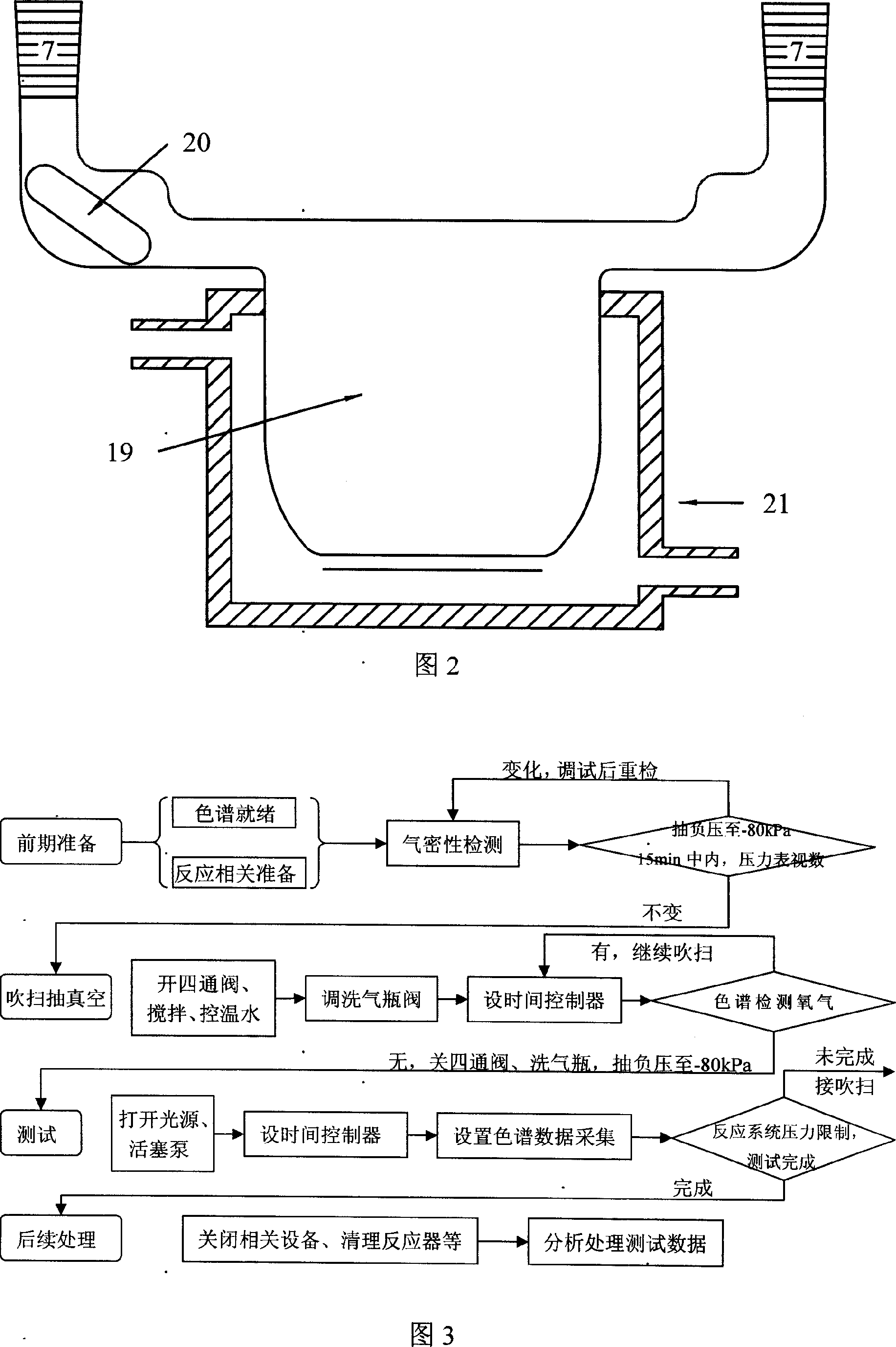
[0034] The photocatalytic reaction negative pressure loop automatic test system of the present invention can be operated according to the flowchart shown in FIG. 3 .
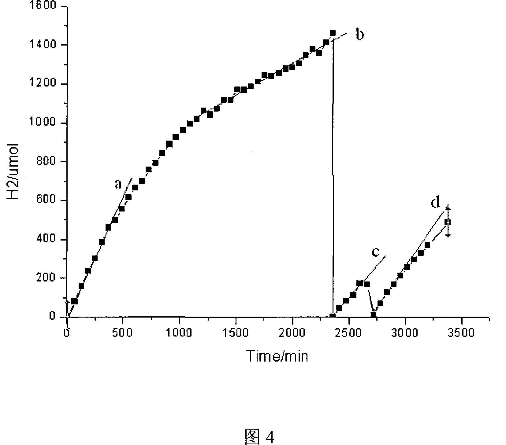
[0035] Example: Catalyst stability investigation under long-term measurement
Login to View More PUM
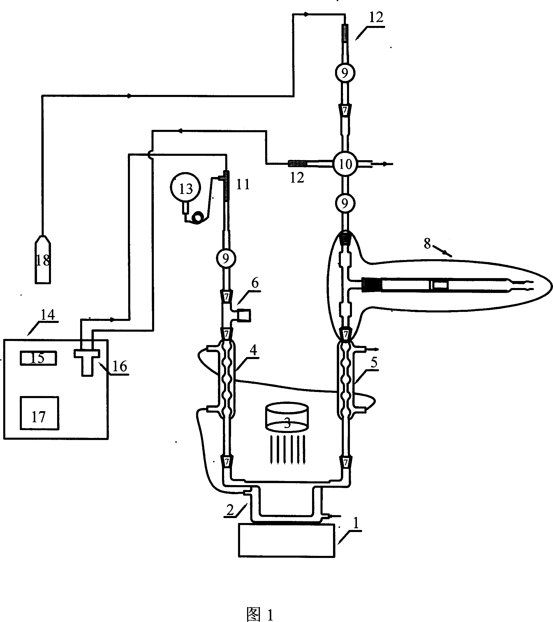
 Abstract
The invention discloses a self-testing system of negative pressure loop of optical catalyzed reaction, which comprises the following parts: reacting part with magnetic stirrer, reactor, xenon lamp source, circulating part with magnetic glass piston pump, spherical glass condenser, gas-phased chromatogram, reactor, blowing vacuum extracting part with ten-shaped four-way vacuum piston, scrubbing bottle, precise vacuum pressure list and vacuum pump, sampling detecting part with gas phased chromatogram, automatic six-way sampling valve, gas-carrier bottle and gas driving bottle, temperature control part with thermostatic circulating pump, reactor temperature control jacket and spherical glass condenser. The invention can estimate the catalytic property of catalyst precisely and in time, which is fit for other optical catalyzed reacting tests in relative to gas participation or generation.
Description
technical field [0001] The invention belongs to a catalytic chemical reaction testing experimental system, in particular to a photocatalytic reaction negative pressure loop automatic testing system. Background technique [0002] It is of great significance for the research of catalysts to test the catalytic activity of catalysts under controllable conditions and the reaction stability under long-term conditions. For photocatalytic reactions, the testing of photocatalysts is particularly important. [0003] In the photocatalytic water splitting reaction, most catalysts are semiconducting, and the basic principle of action is: when the semiconductor photocatalyst is irradiated by sunlight (mainly visible light and ultraviolet light), the electrons inside it are excited to transition from the valence band to Conduction band, so that free electrons and electron holes are generated in the conduction band and valence band, respectively. When the electrons and holes migrate to th...
Claims
Login to View More Application Information
Patent Timeline
 Patent Type & Authority Applications(China)
IPC IPC(8): G01N33/00
CPCY02E60/364Y02E60/36
Inventor 郭烈锦刘欢陈震宇马利静敬登伟梁慧荣刘冠杰张西民
Owner XI AN JIAOTONG UNIV