

Projection display device
A technology of projection display and projection lens, which is applied in the direction of using projection device image reproducer, projection device, instrument, etc. It can solve the problems of single tube that is difficult to display on a large screen, difficult to display on a large screen, and low power, and achieve color Rich, small size, long-lasting effect
- Summary
- Abstract
- Description
- Claims
- Application Information
AI Technical Summary
Problems solved by technology
Method used
Image

Examples
Embodiment 1
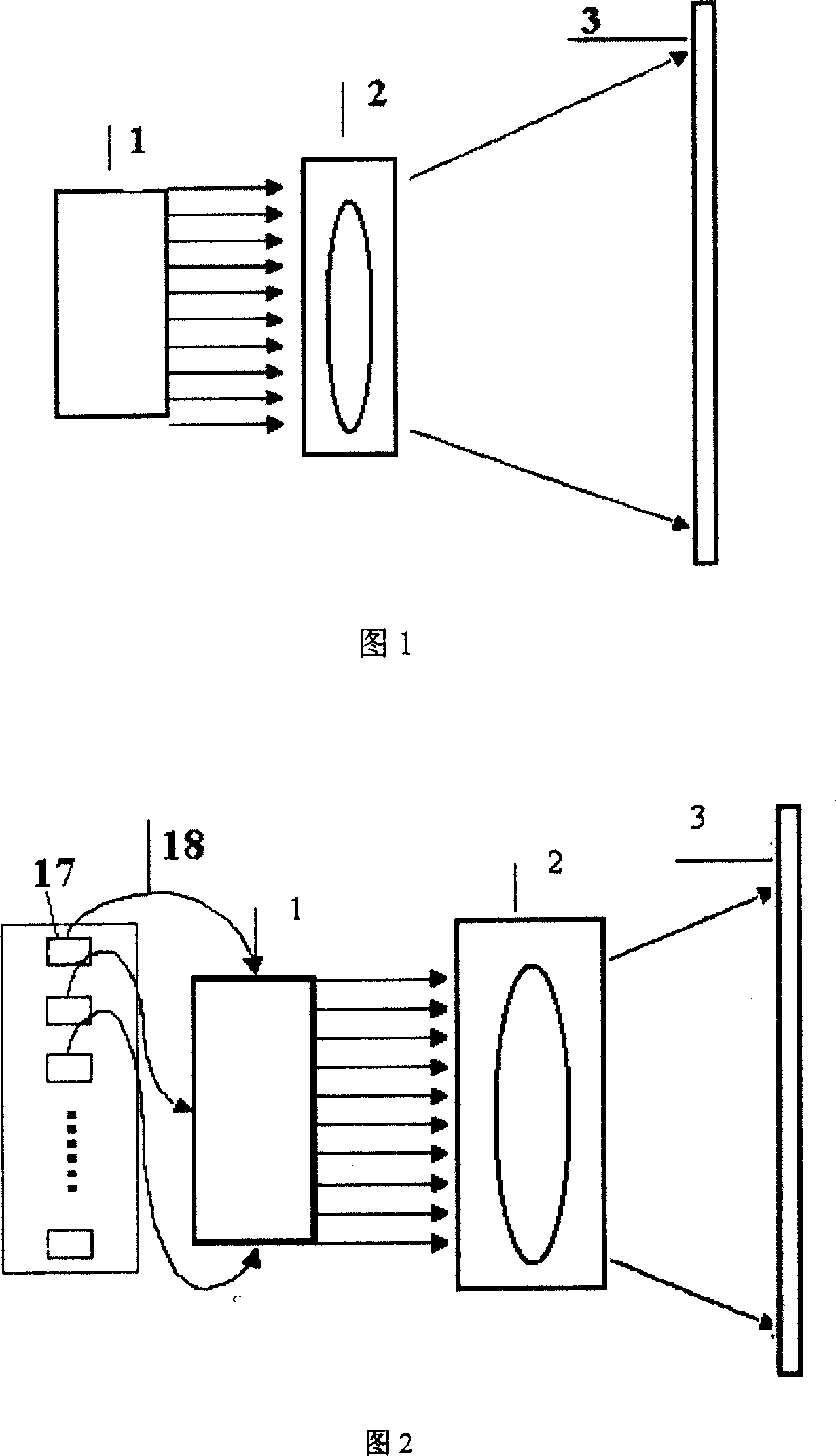
[0044] Make a LED area array color projection display device according to Fig. 1, comprise light source 1, projection lens system 2 and a signal modulator (not shown in the figure), described light source 1 is an LED area array light source constituted by LED array The light beam emitted by the LED area array light source enters the projection lens system 2; the signal modulator is connected with the LED area array light source for loading display signals. in:
[0045] The LED or LD area array of the present invention can directly form an image through projection, and the area of the area array is generally not greater than 0.5 square meters. In this embodiment, the LED area array light source adopts an area array with a resolution of 1024×768, and each pixel is composed of three LEDs of red, green, and blue, and its wavelengths are 670nm, 515nm, and 440nm respectively; The signal is input to the LED area array, and the image is directly displayed by the LED area array, and...
Embodiment 2
[0047]According to Fig. 2, a color projection display device in which LD is coupled into an optical fiber is made, including a light source 1, a projection lens system 2 and a signal modulator (not shown in the figure), and the light source 1 is composed of an LD area array and an optical fiber array , the light emitted by the LD area array is coupled into the optical fiber, and the output end of the optical fiber forms the optical fiber array. The optical fiber array sends light beams into the projection lens system 2; the signal modulator is electrically connected to the LD area array light source for loading display signals.
[0048] The LD area array is composed of 480,000 small LD arrays 17 . Each LD small array 17 is made up of three LDs of red, green and blue, and its wavelength is 670nm, 515nm, 440nm respectively. 10,000 LD small arrays 17 are coupled into 480,000 single-mode optical fibers 18, and then the output ends of the single-mode optical fibers 18 are arranged...
Embodiment 3
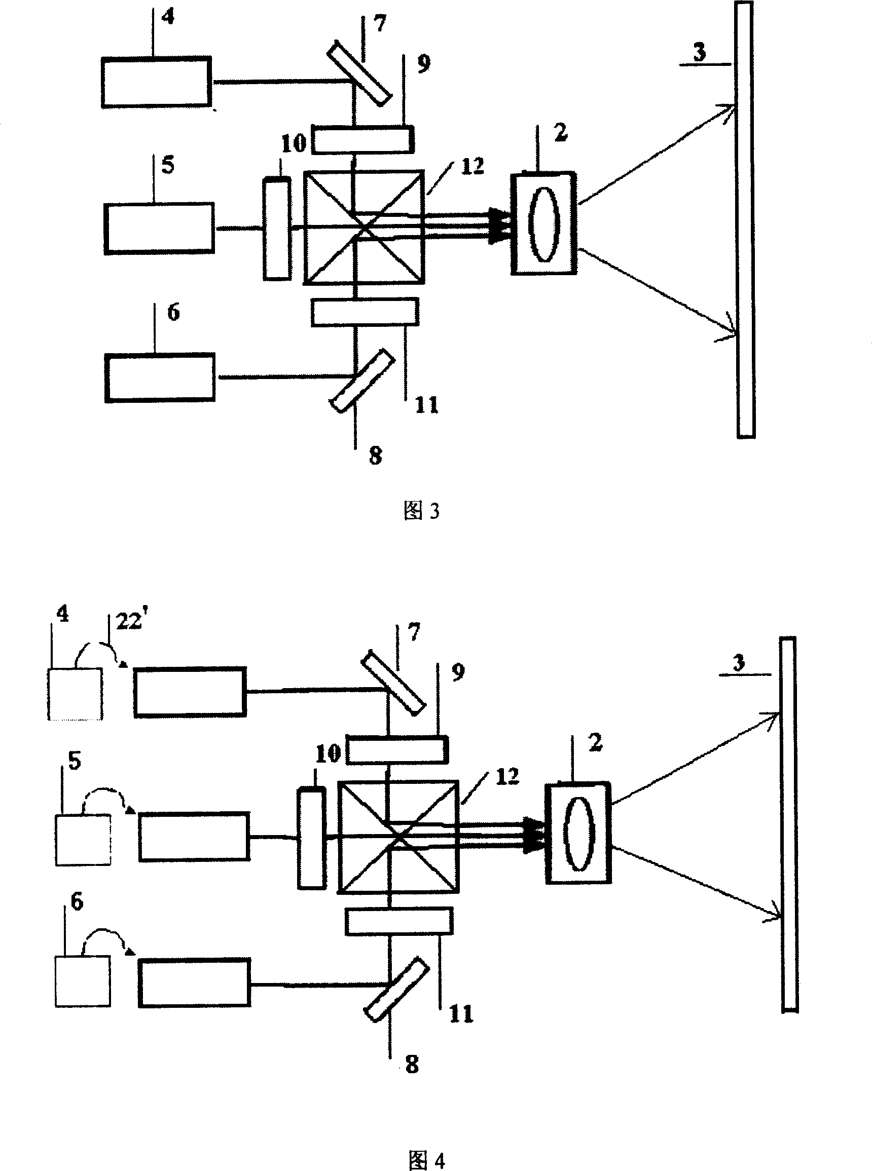
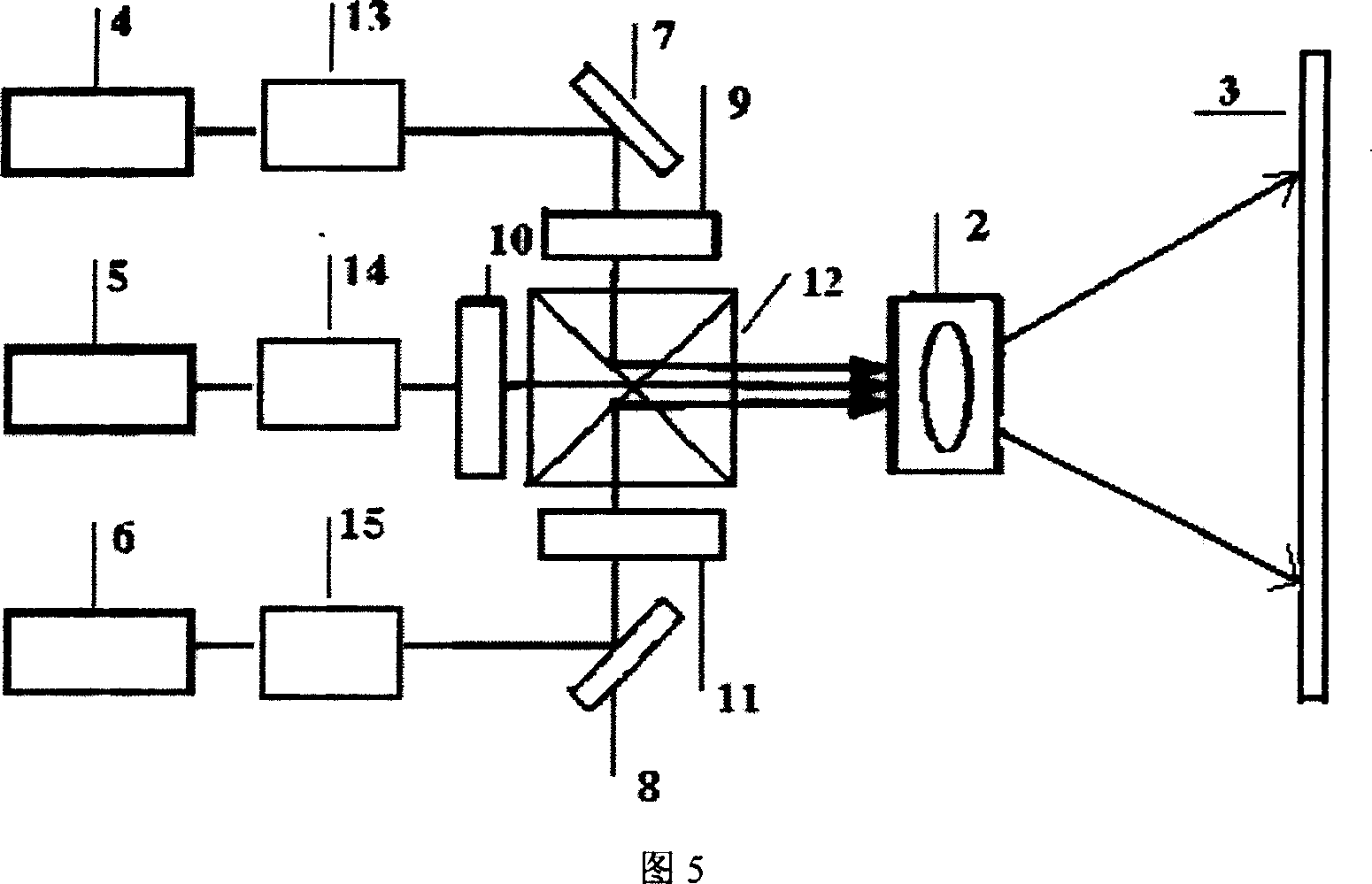
[0050] According to Fig. 3, a projection display device of a three-primary-color LED array is fabricated. It includes a light source 1, a projection lens system 2, a beam combining prism 12, a red light reflector 7 and a blue light reflector 8, and three signal modulators.
[0051] Wherein light source 1 is made up of three LED area array light sources, is respectively red light LED area array 4, green light LED area array 5 and blue light LED area array 6; The three described signal modulators are red light signal modulator 9, green light signal modulator The optical signal modulator 10 and the blue light signal modulator 11 correspond one-to-one to the red LED array 4, the green LED array 5 and the blue LED array 6 respectively, and are arranged in corresponding arrays respectively. On the optical path between the light source and the beam combining prism 12; the light emitted by the red LED array 5 and the blue LED array 6 respectively passes through the red reflector 7 and...
PUM
 Abstract
Description
Claims
Application Information