Membrane separating process for purifying high temperature condensated water
A high-temperature condensed water and membrane separation technology, applied in permeation/dialysis water/sewage treatment, etc., can solve the problems of oil particles clogging pores, small absorption capacity, unstable effect, etc., to achieve high recycling rate, good effluent quality, Good effluent quality
- Summary
- Abstract
- Description
- Claims
- Application Information
AI Technical Summary
Problems solved by technology
Method used
Image
Examples
Embodiment 1
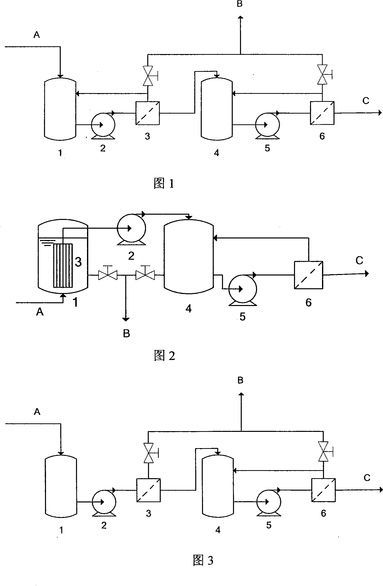
[0024] Embodiment 1 (flow process is as Figure 1)
[0025] Pass 50L steam condensate A at 85°C into the membrane treatment system. The water quality of the steam condensate is shown in the "influent water quality" column of Table 1.
[0026] As shown in Figure 1, the microfiltration or ultrafiltration membrane module 3 adopts a 19-channel tubular ceramic microfiltration membrane with a pore size of 200 nm and a membrane area of 1 m 2 , the pressure conditions required for filtration are provided by the pump 2, the working pressure is 0.25MPa, and the cross-flow filtration method is adopted, that is, the non-permeate circulates between the microfiltration membrane module 3 and the liquid storage tank 1, and the cross-flow membrane surface flow velocity 2.5m / s, under this condition, the stable flux of the ceramic microfiltration membrane is 0.8m 3 / h, the effluent water quality is shown in the column "Pretreatment effluent water quality" in Table 1.
[0027] The effluent fro...
Embodiment 2
[0032] Pass 50L of steam condensate A at 65°C into the membrane treatment system. The water quality of the steam condensate is shown in the "influent water quality" column of Table 2.
[0033] As shown in Figure 2, the microfiltration or ultrafiltration membrane module 3 adopts a polyethersulfone hollow fiber ultrafiltration membrane with a membrane pore size of 20 nm and a membrane area of 8 m 2 , the working pressure is 0.03MPa, the ultrafiltration membrane module 3 is placed in the high-temperature condensed water feed liquid of the liquid storage tank 1, and the dead-end suction negative pressure filtration method is adopted, and the suction pump 2 provides the pressure conditions required for filtration. The average flux of the lower ultrafiltration membrane is 1.2m 3 / h, the effluent water quality is shown in the column "Pretreatment effluent water quality" in Table 2.
[0034] The above-mentioned ultrafiltration membrane effluent enters the intermediate liquid tank 4...
Embodiment 3
[0037] Embodiment 3 (flow process is as Figure 3)
[0038] Pass 50L steam condensate A at 75°C into the membrane treatment system. The water quality of the steam condensate is shown in the "influent water quality" column of Table 3.
[0039] As shown in Figure 3, the microfiltration module 3 adopts a stainless steel tubular microfiltration membrane with a pore size of 0.8 μm and a membrane area of 0.5 m 2 , the working pressure is 0.12MPa, the dead-end filtration method is adopted, and the pressure condition required for filtration is provided by the pump 2. Under this condition, the average flux of the microfiltration membrane is 1.2m 3 / h, the effluent quality is shown in Table 3 "Pretreatment effluent quality".
[0040] The effluent from the microfiltration membrane enters the intermediate liquid tank 4, and is pressurized by the pump 5 to feed the polyethersulfone roll-type nanofiltration membrane module 6, during which a cross-flow filtration cycle is formed. Membrane...
PUM
| Property | Measurement | Unit |
|---|---|---|
| Membrane area | aaaaa | aaaaa |
| Membrane area | aaaaa | aaaaa |
Abstract
Description
Claims
Application Information
 - R&D
- Intellectual Property
- Life Sciences
- Materials
- Tech Scout
- Unparalleled Data Quality
- Higher Quality Content
- 60% Fewer Hallucinations
Browse by: Latest US Patents, China's latest patents, Technical Efficacy Thesaurus, Application Domain, Technology Topic, Popular Technical Reports.
© 2025 PatSnap. All rights reserved.Legal|Privacy policy|Modern Slavery Act Transparency Statement|Sitemap|About US| Contact US: help@patsnap.com

