Electric-controlled diesel oil fuel oil injector driven by telescoping element

A technology of diesel fuel injectors and fuel injectors, which is applied in the direction of engine components, machines/engines, fuel injection devices, etc., to achieve the effects of scientific structure, low cost and improved technical indicators

Inactive Publication Date: 2008-01-02
柳州华威电控技术有限公司
View PDF0 Cites 10 Cited by
  • Summary
  • Abstract
  • Description
  • Claims
  • Application Information

AI Technical Summary

Problems solved by technology

[0003] The object of the present invention is to provide an electronically controlled diesel fuel injector driven by a telescopic element, which can enable the diesel engine to realize several pre-spray and main injection fuel injections in a very short fuel injection time, and reduce the noise of the diesel engine. Various technical indicators of fuel consumption, emission and output power have been improved to solve the above-mentioned problems existing in the existing electromagnetic injectors

Method used


Image

  • Electric-controlled diesel oil fuel oil injector driven by telescoping element
  • Electric-controlled diesel oil fuel oil injector driven by telescoping element
  • Electric-controlled diesel oil fuel oil injector driven by telescoping element

Examples


Embodiment 1

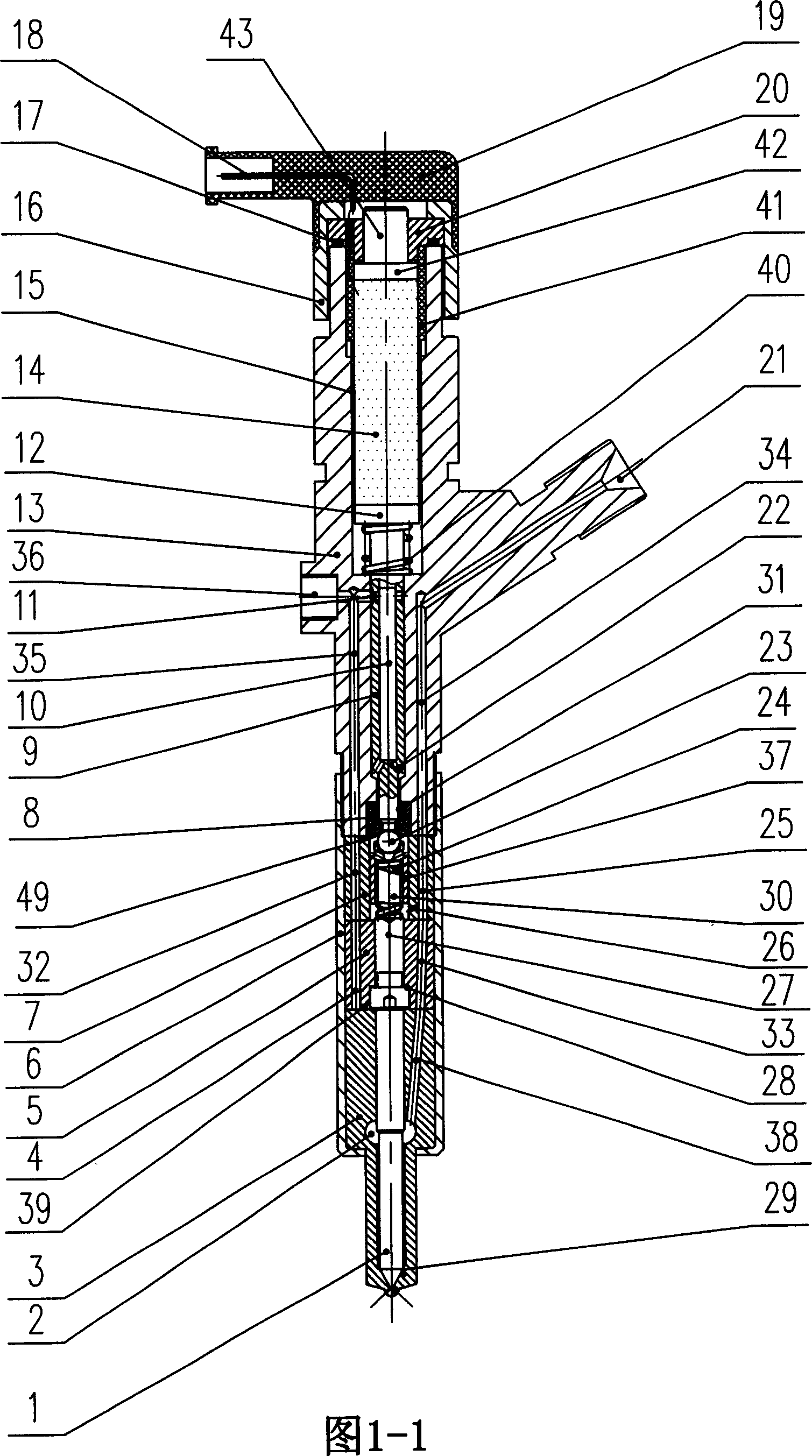
[0030] An electronically controlled diesel fuel injector driven by an electrostrictive element, in which a push rod spring (40), a push rod (9), and a push rod seat (12 ), consisting of an electrostrictive element (14), a plastic spacer (15) covering the outer lower part of the electrostrictive element (14) and an insulating cylinder (41) covering the outer upper part of the electrostrictive element (14) The electrostrictive element assembly, the gasket (42), the upper end cover (20), the axial positioning shaft (43), and then tighten the upper nut (16), and install the ball valve seat at the lower end of the injector housing (13) (8), install the injector assembly (1) and (3), the command plunger (27) and the command plunger valve body (5), the command oil chamber valve body (7) in sequence in the nut sleeve (6) ), spring (24), steel ball seat (37) and steel ball (23), wherein the steel ball (23) and the steel ball seat (37) are welded together, the lower end surface of the i...

Embodiment 2

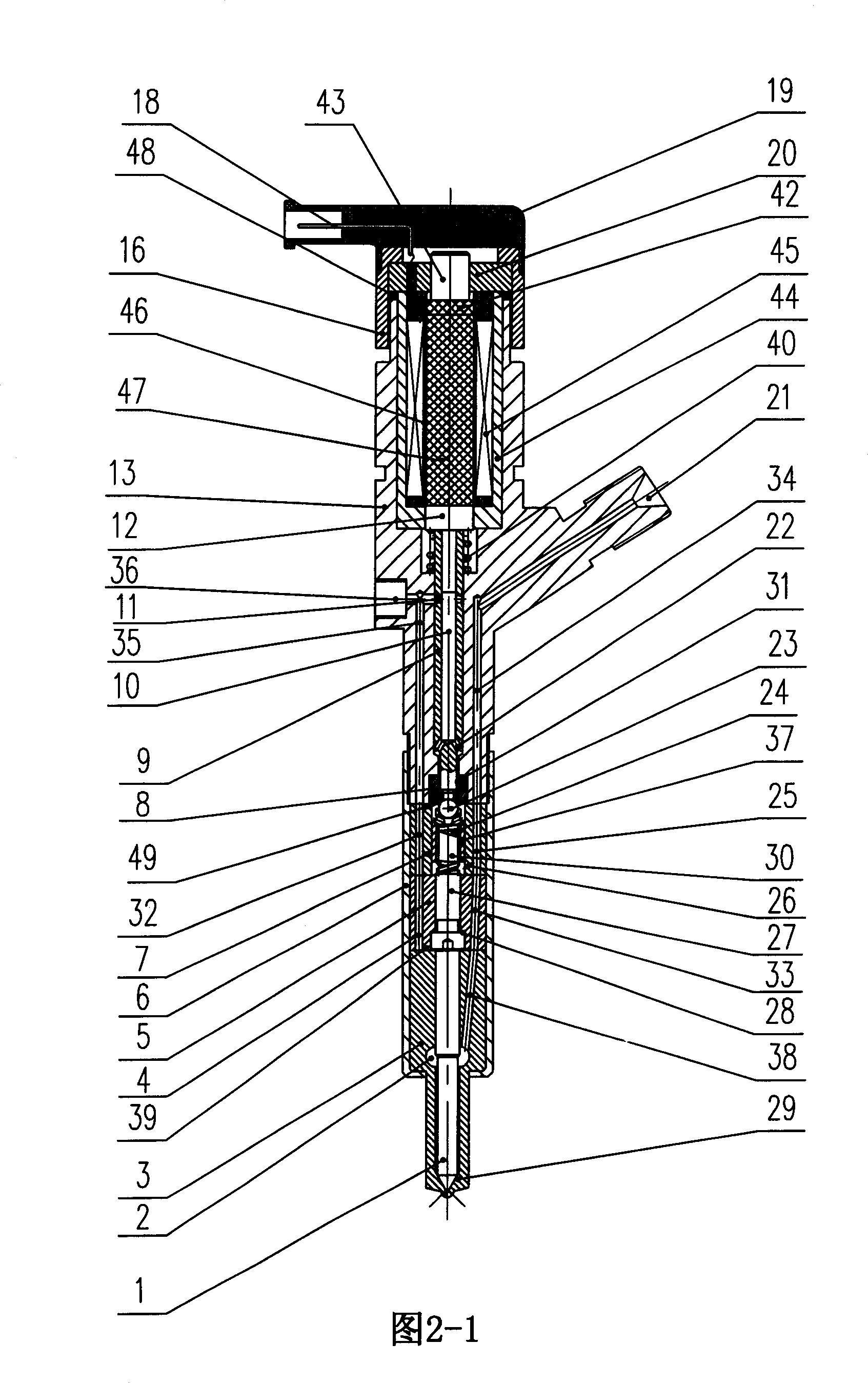
[0042] An electronically controlled diesel fuel injector driven by a magnetostrictive element, its basic structure is the same as that of Embodiment 1, the difference lies in: a push rod seat (12), a gasket ( There is no electrostrictive element assembly between 42), but a wire frame (46) made of a magnetic sleeve (44) and a magnetic wire (45) is installed, placed inside the wire frame (46), and positioned at the push rod seat. (12), the magnetostrictive element assembly composed of the magnetostrictive element (47) between the spacers (42), the push rod spring (40), Push rod (9), push rod seat (12), and the wire frame (46) that is wound with electromagnetic wire (45) by magnetic conduction cover (44), is positioned at the magnetostrictive element (47) on the wire frame (46) ) composed of a magnetostrictive element assembly (see Figure 2).

[0043] The fuel injector housing (13) is also a cylinder with unequal diameters like the housing (13) in Embodiment 1, with a large uppe...


PUM


Abstract

The invention discloses an electric control diesel injector of adjustable element drive, which is characterized by the following: comprising belt entering, injector casing of back oil passage and nut cover; assembling push bar spring, push bar, push bar seat, adjustable element component, pad, upper end lid and axial locating axle in the casing along axially; arranging ball valve seat on the lower end of the casing; assembling fuel spray nozzle double element, dictating trunk piston, steel ball seat, dictating trunk piston valve body, dictating oil cavity valve body, spring and steel ball; loading element to back injector casing; screwing up with the nut cover; connecting each element end face tightly; constructing the device. This invention can decrease cost of diesel machine electric control injector and preparing hardness.

Description

Technical field: [0001] The invention relates to a fuel injector used in an electronically controlled diesel engine fuel injection system, in particular to an electronically controlled diesel fuel injector driven by a telescopic element using common rail electronically controlled fuel injection technology. Background technique: [0002] At present, the fuel supply system of the common rail electronically controlled diesel engine uses an electromagnetic injector to inject high-pressure diesel into the cylinder. Since the electromagnetic coil of the electromagnetic injector has a certain degree of inductance when it works, it is difficult to respond to the requirements of higher injection frequency. , restricting the development of diesel engines in the direction of lower fuel consumption, cleaner emissions, and lower noise. Contents of the invention [0003] The object of the present invention is to provide an electronically controlled diesel fuel injector driven by a teles...

Claims


Application Information

Patent Timeline
Patent Type & Authority Applications(China)
IPC IPC(8): F02M51/06
Inventor 林小东彭千
Owner 柳州华威电控技术有限公司
Why Eureka
Try Eureka