
Pumping unit balance adjusting apparatus and pumping unit balance structure adjusting method

A technology of balance adjustment and pumping unit, which is applied in the testing of machine/structural components, static/dynamic balance testing, instruments, etc., and can solve the problems of narrow application area, waste of electric energy, and few functions.

Inactive Publication Date: 2008-01-16
刘克文
View PDF2 Cites 26 Cited by
  • Summary
  • Abstract
  • Description
  • Claims
  • Application Information

AI Technical Summary

Problems solved by technology

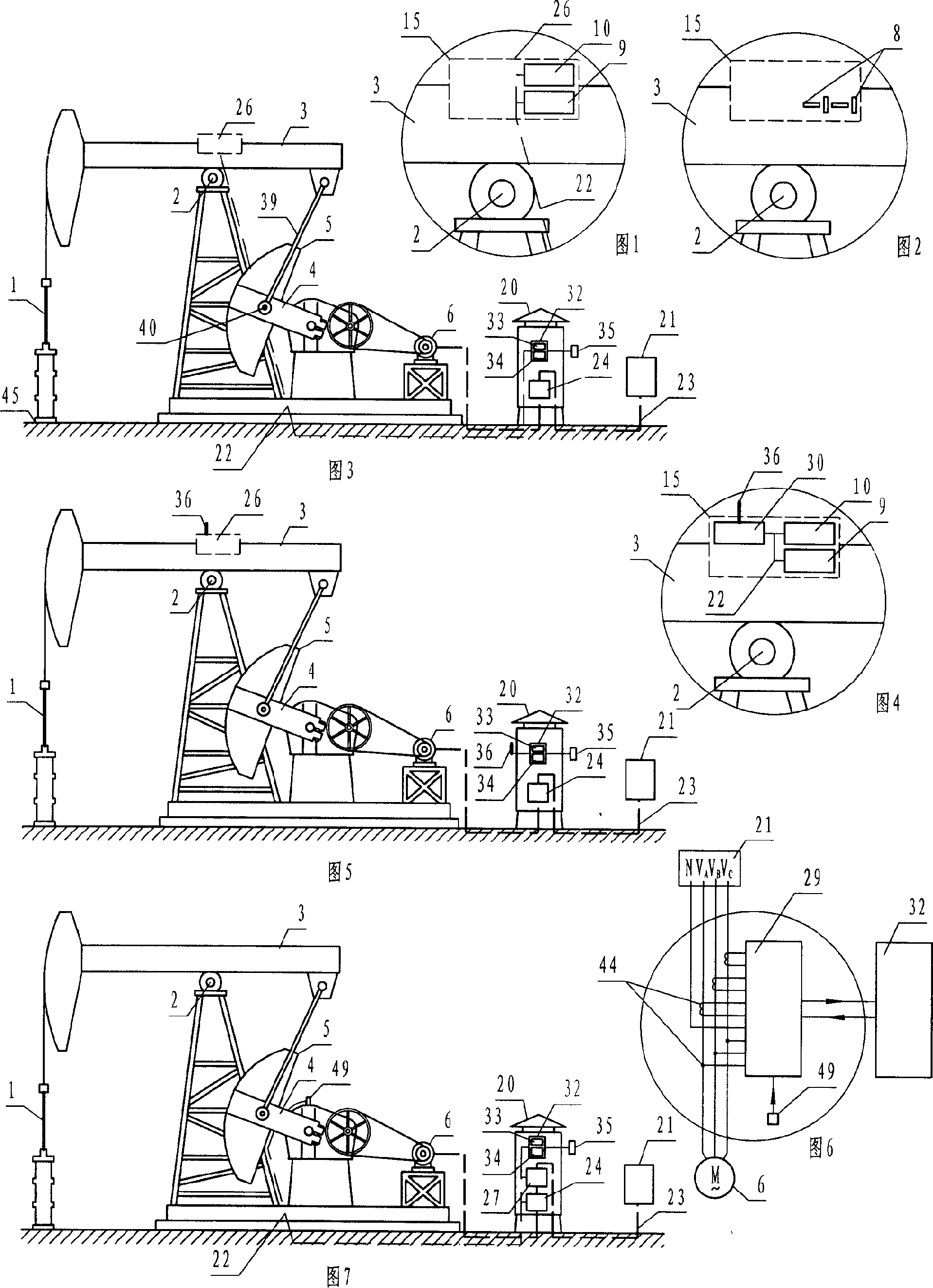
[0005] The disadvantages of the "balanced current method" are: 1. The "actually measured parameter" is the current, and the "actually adjusted parameter" is the displacement, which belongs to the "adjustment indirect parameter". The definite relationship between the displacement and the current cannot be given. , based on experience, make a rough estimate of the displacement of the balance block, and complete it step by step through multiple trial adjustments. 2. The theory and practice indicate that the “balanced current method” is adjusted very accurately, and the current balance is 100% achieved, which is not the most power-saving state (see for details, (4) on page 316 of "Petroleum Industry Energy Conservation Technology" —Petroleum Industry Press August 2000 first edition); 3, due to the above reasons, many beam pumping units in operation are not well balanced, thus wasting a large amount of electric energy
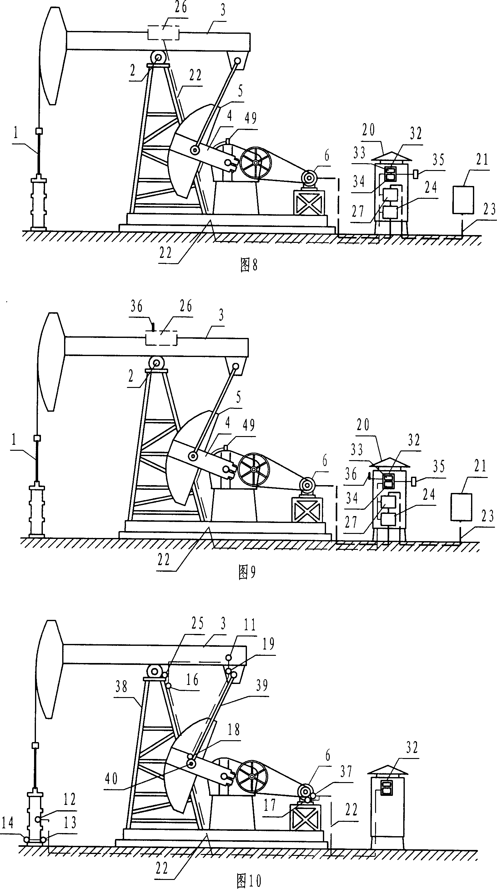
[0011] 1. The sensor is installed on the unstable moving object - the polished rod system. During the operation, the unstable flexible multi-dimensional vibration (caused by the flexible transmission part - the steel wire rope) is likely to cause damage to the instrument;
[0012] 2. The sensor is above the wellhead, which is a dangerous area. In the workover operation, if the instrument is not dismantled, it is easy to be collided by the dismantled and installed tubing and the running equipment, and it is also easy to be splashed by crude oil and high-pressure cleaning water. Contaminated, more likely to cause damage to the instrument;
[0013] 3. It can only form a single-color dynamometer diagram, and the information is not rich;
[0015] In addition, the data acquisition and transmission units of some oil production measurement and control systems have few functions and narrow application areas. People expect that one unit can monitor more parameters, so as to avoid the establishment of multiple measurement and control systems, resulting in repeated investment.

Method used


Image

  • Pumping unit balance adjusting apparatus and pumping unit balance structure adjusting method
  • Pumping unit balance adjusting apparatus and pumping unit balance structure adjusting method
  • Pumping unit balance adjusting apparatus and pumping unit balance structure adjusting method

Examples


Embodiment 1

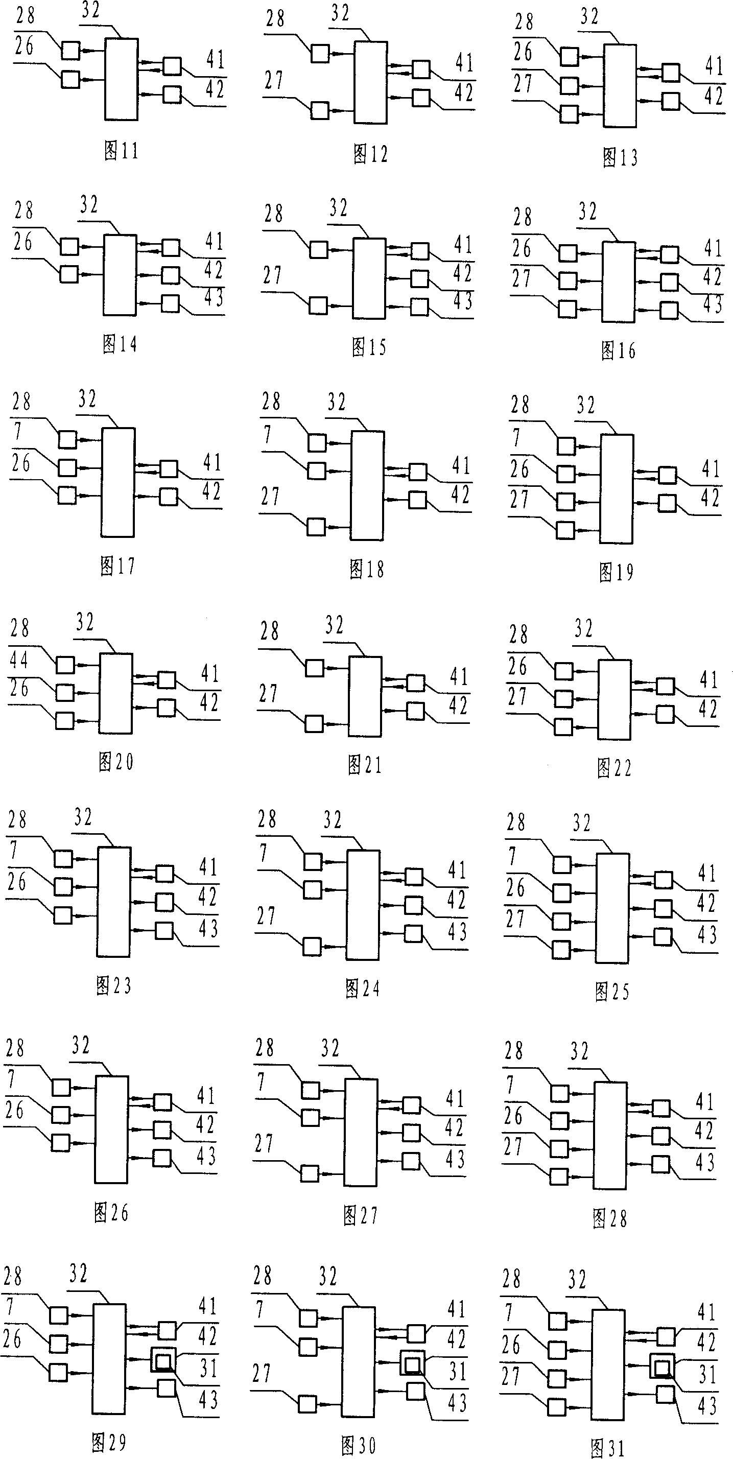
[0161] Embodiment 1, as shown in Figure 11, belongs to a pumping unit balance regulator adopting a "beam structure for displaying work".

[0162] It consists of a data input device 28, a beam display structure 26, a central processing unit 32, a storage device 41, an output device 42, etc., and its working process is as follows:

[0163] The parameters obtained by the data input device 28 and the beam display structure 26 are transmitted to the central processing unit 32, and the central processing unit 32 obtains "adjustment direct parameters" through data processing, and is transmitted to the storage device 41 for storage and transmitted to the The output device 42 displays.

Embodiment 2

[0164] Embodiment 2, as shown in Figure 12, belongs to a pumping unit balance regulator adopting an "electrical power indicator structure".

[0165] It consists of a data input device 28, an electric power indicator structure 27, a central processing unit 32, a storage device 41, an output device 42, etc., and its working process is as follows:

[0166] The parameters obtained by the data input device 28 and the electric indicator structure 27 are transmitted to the central processing unit 32, and the central processing unit 32 obtains "adjustment direct parameters" through data processing, and transmits to the storage device 41 for storage, and transmits to the The output device 42 displays.

Embodiment 3

[0167] Embodiment 3, as shown in Figure 13, belongs to a pumping unit balance regulator adopting a "complementary structure".

[0168] It consists of a data input device 28, a beam indicator structure 26, an electric indicator structure 27, a central processing unit 32, a storage device 41, an output device 42, etc. Its working process is as follows:

[0169] The parameters obtained by the data input device 28, the beam display structure 26, and the electric display structure 27 are transmitted to the central processing unit 32, and the central processing unit 32 obtains the "thinning control" through "complementary comprehensive processing" of the data. parameters", transmitted to the storage device 41 for storage, and transmitted to the output device 42 for display.


PUM


Abstract

The invention discloses a balance adjustment device for oil pumping machine and balanced structure adjustment method of oil pumping machine, by which the balanced structure adjustment is changed from using indirect parameter-electric current to using direct parameter-displacement, so that the adjustment is accurate and rapid, and the energy is remarkably saved. The invention also discloses an oil extraction control device, a color power indicator, an oil extraction measurement meter, an oil extraction integrated protection device, an oil extraction integrated testing and diagnosis control device, and a data acquisition and transmission unit for an oil extraction measurement and control system. The color power indicator provides a novel mean and method for diagnosis of oil pumping machine, which remarkably improves the effectiveness of diagnosis. The oil extraction integrated diagnosis control device and the data acquisition and transmission unit for the oil extraction measurement and control system have the advantages of high degree of automation, more monitored and controlled parameters, and large protection range; can perform onsite automatic acquisition and control and can perform long-distance automatic acquisition and control in management center; and provides a fundamental mean with high feasibility for realizing automated management of the full oil field.

Description

technical field [0001] The present invention relates to: 1. An instrument for measuring and monitoring the balance state of a pumping unit, which is used for adjusting the balance structure of the pumping unit; 2. An instrument for measuring the liquid supply state of an oil well, and controlling the start and stop of the pumping unit according to the measurement results, 3. An instrument for measuring and monitoring curves and graphics reflecting the working state of pumping wells and related data, especially related to measuring and monitoring various indicators reflecting the working state of oil pumps 4. A measuring instrument for measuring power consumption and liquid production in oil extraction; 5. A monitoring instrument based on abnormal conditions such as power supply, pumping unit motor, oil pumping tools, and on-site theft , an instrument that automatically implements alarm and protection; 6. A comprehensive test, diagnosis, and control instrument for oil productio...

Claims


Application Information

Patent Timeline
IPC IPC(8): E21B43/00E21B44/00E21B47/00G01M1/14E21B47/009
Inventor 刘克文
Owner 刘克文
Learn More