Biochemical inspection device and biochemical inspection method
An inspection device and inspection method technology are applied in the field of devices for analyzing biochemical reactions, and can solve problems such as reducing and increasing the burden on inspectors, failing to obtain fluorescence image inspection efficiency, and the like
Inactive Publication Date: 2008-01-23
OLYMPUS CORP
1 Cites 3 Cited by
AI-Extracted Technical Summary
Problems solved by technology
However, in this method, for example, when the luminescence intensity of each array element of the array for biochemical testing is significantly reduced due to the wrong solution of the biochemical substance by the examiner, a large amount of ac...
Method used
As can be seen from the above description, according to the biochemical inspection device of the present embodiment, because the fluorescent image of the biochemical inspection array recorded (saved) is within the required intensity range, useless images can be prevented from being recorded (saved). ...
Abstract
Firstly, imaging is performed with an exposure time of ExpStart. When the maximum intensity value of all the pixels in the image is smaller than TransStart, the exposure time is increased and imaging is performed again. After this, increase of the exposure time and imaging are repeatedly performed until the maximum intensity value of all the pixels of the imaged optical image reache the TransStart. When the maximum intensity value has reached TransStart, the image is transferred to a computer and recorded on a hard disc. The number of recorded discs is counted. After this, increase of the exposure time, imaging, image data transfer and recording, and the number of recorded discs are repeatedly performed. The imaging is terminated when the minimum intensity value in an area smaller than the entire area of the optical image has become greater than TransEnd or the number of recorded discs has become greater than TransPicts or the exposure time has become greater than MaxExpTime.
Application Domain
Color/spectral properties measurementsFluorescence/phosphorescence
Technology Topic
PhysicsMaximum intensity +3
Image
Examples
- Experimental program(1)
Example Embodiment
[0024] Hereinafter, embodiments of the present invention will be described with reference to the drawings.
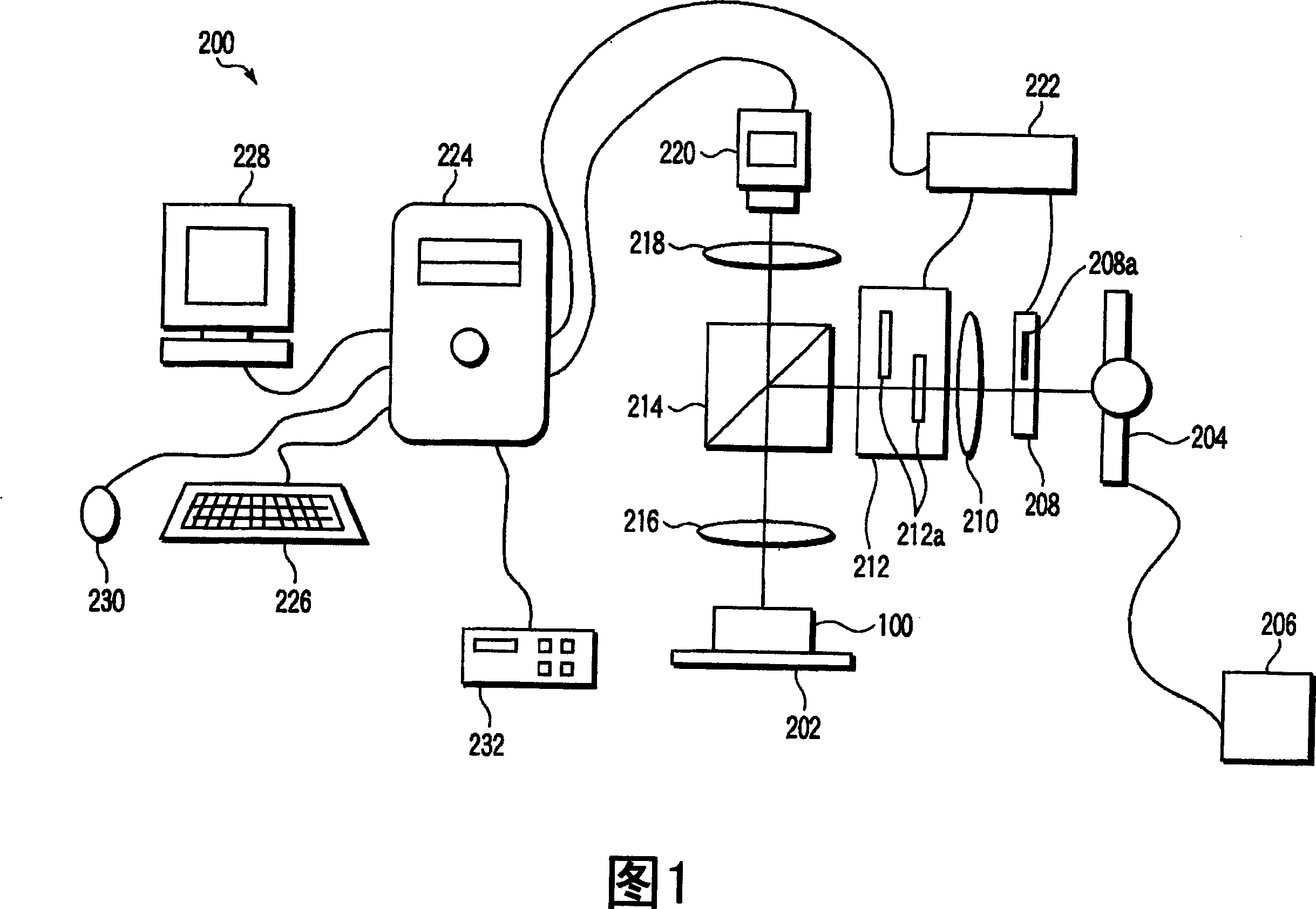
[0025] Fig. 1 shows the configuration of a biochemical inspection apparatus according to an embodiment of the present invention. In FIG. 1, the excitation light source 204 is various lamps such as a mercury light source or an LED, etc., and is connected to the power supply unit 206. On the optical path of the excitation light emitted from the excitation light source 204, a shutter unit 208 containing a shutter 208, a lens 210, a filter unit 212 containing two excitation filters 212a, and a dichroic mirror 214 are arranged. On the reflection light path of the dichroic mirror 214, an objective lens 216 and a stage 202 on which the array 100 for biochemical inspection is mounted are arranged. In addition, an imaging lens 218 and a CCD camera 220 as an imaging element are arranged on the transmission light path of the dichroic mirror 214. The CCD camera 220 contains a buffer memory (not shown) capable of temporarily storing at least one captured image, and a signal processor (not shown) capable of performing image calculations such as signal strength detection of the image on the buffer memory. The shutter unit 208 and the filter unit 212 can be controlled by the computer 224 via the universal control box 222. The stage 202 can be electrically determined in the XY direction, and can be controlled by the computer 224 via the stage controller 232. A keyboard 226, a monitor 228, and a mouse 230 are connected to the computer 224.
[0026] In other words, the biochemical inspection apparatus 200 includes a stage 202 that supports the biochemical inspection array 100, an excitation light source 204 that emits excitation light, and transmits the excitation light toward the biochemical inspection array 100 while reflecting the biochemical inspection. A dichroic mirror 214 using the fluorescence generated by the array 100, and a CCD camera 220 for taking a fluorescence image of the array 100 for biochemical inspection. Here, the fluorescent image is a type of optical image, and the so-called optical image is an image obtained by using various light signals such as fluorescence, phosphorescence, chemiluminescence, bioluminescence, scattered light, and reflected light.
[0027] In addition, the biochemical inspection apparatus 200 includes a shutter unit 208 for blocking the excitation light, a lens 210, and a filter unit 212 for selecting the wavelength of the excitation light. The shutter unit 208, the lens 210, and the filter unit 212 are sequentially arranged on the optical path from the excitation light source 204 to the dichroic mirror 214.
[0028] In addition, the biochemical inspection apparatus 200 includes an objective lens 216 located between the dichroic mirror 214 and the stage 202, and an imaging lens 218 located between the dichroic mirror 214 and the CCD camera 220.
[0029] In the optical system constructed in this way, the excitation light source 204, the shutter unit 208, the lens 210, the filter unit 212, the dichroic mirror 214, and the objective lens 216 constitute an illumination mechanism for irradiating the array 100 for biochemical inspection with excitation light . In addition, the objective lens 216, the imaging lens 218, and the CCD camera 220 constitute a photographing mechanism for photographing a light image emitted by the biochemical inspection array 100.
[0030] In addition, the biochemical inspection apparatus 200 includes a power supply unit 206 for driving the excitation light source 204, a stage controller 232 for driving the stage 202, and a general control box for driving the shutter unit 208 and the filter unit 212 222.
[0031] In addition, the biochemical inspection apparatus 200 includes a computer 224 that controls the CCD camera 220, the stage controller 232, and the general control box 222. A keyboard 226, a monitor 228, and a mouse 230 are connected to the computer 224 as a user interface. The computer 224 is equipped with a hard disk, which constitutes a recording mechanism for storing the captured optical image.
[0032] 2 and 3 show an array for biochemical inspection performed by the biochemical inspection apparatus shown in FIG. 1. The array 100 for biochemical inspection is a three-dimensional array, and as shown in FIG. 2, it has a porous three-dimensional substrate 102 and a plurality of probe array elements (probe points) 106 formed on the three-dimensional substrate 102. The probe array elements 106 are arranged two-dimensionally on the three-dimensional substrate 102, and array elements for position detection (dots for position detection) 104 are formed on the four corners of the arrangement area of the probe array elements 106. The three-dimensional base material 102 has a plurality of through holes. As shown in FIG. 3, a probe 110 that reacts with a specific substance is solid-phased on the inner wall of the through hole 108 in the probe array element 106. The probe array element (probe spot) 106 is formed, for example, by dispensing a necessary amount of a solution containing probes onto the three-dimensional substrate 102.
[0033] The multiple probe array elements 106 on the three-dimensional substrate 102 include multiple types. Each probe array element 106 includes probes 110 of the same type. If the probes 110 react with a specific substance, they will emit specific fluorescence when irradiated with specific excitation light.
[0034] The biochemical inspection device 200 is controlled by a control program operating on the computer 224. In other words, the computer 224 contains a control program for controlling the entire biochemical inspection device 200. The control program reads the operation of the control program itself and the operation parameters of each unit from the original data file shown in FIG. 4 to control the entire biochemical inspection device 200.
[0035] Figure 4 shows a part of the original data file is taken out. The inspector or the administrator of the device can simply correct and change the original data file through a general editing program. That is, the inspector or the device manager can operate the keyboard 226 while looking at the monitor 228, and also operate the mouse 230 if necessary, thereby easily correcting and changing the original data file. The original data file contains various parameters, and the monitor 228, the keyboard 226, and the mouse 230 constitute an input mechanism for arbitrarily setting the parameters in the original data file.
[0036] The parameters shown in FIG. 4 are imaging parameters when the fluorescence image of the biochemical inspection array 100 is captured by the CCD camera 220.
[0037] ExpStart is the initial value of the exposure time (the charge accumulation time of the CCD) when the CCD camera 220 captures the fluorescence image of the biochemical inspection array 100. When the examiner instructs the start of the imaging of the fluorescence image of the biochemical inspection array 100, the CCD camera 220 changes the exposure time so as to gradually extend from the initial value shown at that time, while repeatedly imaging the biochemical inspection array 100. The exposure time is not limited to this, such as 10×2 n-1 (n=1, 2,...) The ratio of [ms] changes.
[0038] TransStart is a standard value used by the CCD camera 220 to determine the start of recording (saving) the pixel intensity value of the fluorescence image. That is, when the intensity value of the brightest pixel among the total pixels of the fluorescence image of the biochemical inspection array 100 taken by the CCD camera 220 reaches the TransStart value or more, the CCD camera 220 starts to transmit the image data to the computer 224, and accordingly, The storage device (the hard disk in the computer 224) starts recording (saving) the image data.
[0039] TransEnd is a standard value of the pixel intensity value used by the CCD camera 220 to determine the end of recording (saving) of the fluorescence image. That is, when the intensity value of the darkest pixel among the pixels in the center near the area smaller than the entire area of the fluorescent image of the biochemical inspection array 100 taken by the CCD camera 220 is greater than the value of TransEnd, the image transmission to the computer 224 is ended. According to the data, the storage device (the hard disk in the computer 224) ends the recording (saving) of the image data.
[0040] TransPicts is a standard value of the number of recording (saving) sheets used by the CCD camera 220 to determine the end of recording (saving) of the fluorescence image. That is, when the number of fluorescent images of the biochemical inspection array transferred to the computer 224 by the CCD camera 220 is greater than the TransPicts value, the image data transfer to the computer 224 is finished, and accordingly, the storage device (the hard disk in the computer 224) End the recording (saving) of image data.
[0041] MaxExpTime is a standard value of the exposure time used by the CCD camera 220 to determine the end of recording (saving) of the fluorescence image. That is, when the exposure time of the CCD camera 220 for capturing the fluorescence image of the biochemical inspection array 100 is greater than the MaxExpTime value, it ends the image data transmission to the computer 224, and correspondingly, the storage device (the hard disk in the computer 224) ends the image data Record (Save).
[0042] Next, the operation of the biochemical inspection apparatus 200 will be described.
[0043] As a preparation for the biochemical examination, the examiner prepares a solution containing, for example, two biochemical substances labeled with dichromatic fluorescent molecules (or chemiluminescent molecules). At this time, the examiner prepared solutions of two biochemical substances to be compared with the same concentration, one labeled with FITC and the other labeled with rhodamine. If these labeling substances are a combination of substances with different fluorescence wavelengths, they may also be other substances. After that, the prepared solutions of the two biochemical substances were mixed and stirred at a volume ratio of 1:1 to prepare a mixed solution of biochemical substances. The mixing ratio can be changed according to the characteristics of the solution of the two biochemical substances and the labeling substance.
[0044] The examiner supplies a mixed solution of biochemical substances to the biochemical inspection array 100 to specifically react with the probe. At this time, the observer uses the biochemical inspection apparatus 200 shown in FIG. 1 to observe, arranges the biochemical inspection array 100 on the stage 202, and similarly supplies a mixed solution of biochemical substances to the surface thereof. As a result, a specific binding reaction occurs between the probes in the probe array element 106 on the biochemical inspection array 100 and the biochemical substance contained in the mixed solution. As a result, the number of fluorescent molecules (or chemiluminescent molecules) corresponding to the intensity of the reaction in each probe array element 106 is indirectly bound to the probe.
[0045] The examiner removes unreacted biochemical substances from the array 100 for biochemical inspection. At this time, the examiner removes unbound biochemical substances from each of the probe array elements 106 of the biochemical inspection array 100 after the above-mentioned binding reaction. Generally, a method of washing using a washing liquid is used, but when the reaction carrier has a three-dimensional structure, it is also possible to remove each solution by a pump or the like without using the washing liquid. However, it can of course be removed more reliably by using washing liquid.
[0046] The examiner operates the computer 224 via the monitor 228 in order to capture the fluorescence image of the biochemical inspection array 100 for each labeled substance with the CCD camera 220. If the examiner clicks on the "Shooting" button displayed on the monitor 228 with the mouse 230, the computer 224 sends an instruction to the general control box 222 to switch the two excitation filters 212a built in the filter unit 212, and then An excitation filter corresponding to the color of the desired fluorescent molecule is arranged on the illumination light path. Similarly, the computer 224 opens the shutter 208a built in the shutter unit 208, and sends instructions to the general control box 222. Accordingly, the excitation light from the excitation light source 204 passes through the lens 210 and the excitation filter 212a, is reflected by the dichroic mirror 214, and is irradiated on the entire upper surface of the biochemical inspection array 100 via the objective lens 216. As a result, the fluorescence generated by the fluorescent molecules in each probe array element 106 is introduced into the CCD camera 220 after passing through the objective lens 216, the dichroic mirror 214, and the imaging lens 218.
[0047] The CCD camera 220 gradually increases the exposure time (accumulation time) from the initial value indicated by ExpStart written in the initial data file, and repeats shooting. In this embodiment, ExpStart is 10ms, and the exposure time (cumulative time) is 10×2 n-1 (n=1, 2...) The proportion of ms increases. When the shooting is over, a scan is performed to determine whether the maximum value of the total pixel intensity of the captured fluorescence image reaches or exceeds the pixel intensity written in the original data file as TransStart.
[0048] The CCD camera 220 does not transmit image data to the computer 224 when the maximum intensity value of the total pixels of the image is less than TransStart. Fig. 5A shows an image taken immediately after the start of shooting. That is, it shows an image taken with an exposure time of 10 ms. In the image of FIG. 5A, the maximum intensity value of the total pixel is less than TransStart. Therefore, the image data of FIG. 5A in the CCD camera 220 will not be transmitted to the computer 224. The CCD camera 220 repeats the same action until the maximum intensity value of the total pixels of the image reaches above TransStart.
[0049] The CCD camera 220 starts to transmit image data to the computer 224 when the maximum intensity value of the total pixels of the image reaches above TransStart. FIG. 5B shows the image just after the maximum intensity value of the total pixels of the image reaches above TransStart. In the image in FIG. 5B, the maximum intensity value of the total pixels of the image is above TransStart, and two probe array elements appear. Therefore, the CCD camera 220 transmits the image data of FIG. 5B to the computer 224. The transferred image data is recorded (saved) in the hard disk in the computer 224.
[0050] The CCD camera 220 continuously transmits image data to the computer 224 while the minimum intensity value in the region near the center which is smaller than the entire area of the fluorescence image is equal to or less than TransEnd. As the exposure time increases, many probe array elements gradually appear in the fluorescence image of the biochemical inspection array 100 as shown in FIG. 5C, FIG. 5D, and FIG. 5E.
[0051] The CCD camera 220 stops transmitting image data to the computer 224 when the minimum intensity value in an area smaller than the entire area of the fluorescence image is greater than TransEnd. Thus, the recording (saving) of the image data to the hard disk in the computer 224 is completed.
[0052] At this time, you can also temporarily send the image data to the computer to determine whether to save it. In this case, there is no need for a signal processor for image calculation in the CCD camera.
[0053] More preferably, when the fluorescent image of the biochemical inspection array 100 is taken while the image data is being transmitted to the computer 224, even in a state where the illumination light is not illuminated for each exposure time, that is, when the shutter unit 208 is closed Shooting is also performed, and its image data is transferred to the computer 224. Then, the computer 224 performs calculation of subtracting the image taken with the shutter unit 208 closed from the fluorescence image of the biochemical inspection array 100 under the same exposure time as the illumination light, and removes the The processing of dark noise generated by the CCD camera 220 itself. In addition, the noise removal processing can also be performed in the CCD camera 220, and the processed image can be transmitted to the computer 224. If you do this, the transfer process can be completed once, so the processing speed is further improved.
[0054] Normally, if the fluorescence image of the biochemical inspection array 100 is taken while prolonging the exposure time, the aberration of the illumination optical system or the aberration of the observation optical system (the shooting optical system of the CCD camera in this embodiment) will affect the effect, such as From the changes in FIGS. 5D to 5E or as shown in FIG. 6, it can be seen that the intensity unevenness occurs from the central part to the outer peripheral part. As a result, even probe array elements with the same amount of luminescence fluorescence at the center part and the peripheral part will be photographed with different intensity values when photographed by the CCD camera 220, and accurate biochemical inspection cannot be performed. Therefore, the computer 224 calculates the correction coefficient from the uneven distribution of the illumination intensity of the biochemical inspection array 100. For the image that has been recorded (saved), the calculated correction coefficient is used to determine the fluorescence emission of all probe array elements at each exposure time The intensity is corrected. In other words, the computer 224 constitutes a correction mechanism that corrects the fluorescence emission intensity of all the probe array elements at each exposure time using the correction coefficient calculated from the uneven distribution of the illumination intensity for the saved image.
[0055] In this embodiment, as an image for calculating the correction coefficient, an image transmitted to the computer 224 just before the minimum value of the pixel intensity in an area smaller than the entire area of the fluorescence image becomes greater than TransEnd. This is because the dynamic range of the CCD camera 220 is effectively used to obtain a more accurate correction coefficient. The fluorescence image of the biochemical inspection array 100 obtained at this time is, for example, the image shown in FIG. 5E. In this state, since the probe array elements emit fluorescent light, the image is filtered and removed by image interpolation. Pin array elements are used to create the correction coefficient calculation image shown in FIG. 6. The correction coefficient is obtained from this correction coefficient calculation image.
[0056]Normally, through the above-mentioned series of operations, a fluorescent image of the biochemical inspection array 100 can be taken without any problem. However, when the examiner makes a mistake in the mixed solution of biochemical substances, or when the probe array element is not correctly prepared, the correct binding reaction cannot be performed in the biochemical inspection array 100. As a result, the probe array element may not Fluorescence is emitted as expected. At this time, it takes quite a long time until the maximum intensity in the biochemical inspection array 100 reaches a pixel intensity greater than the pixel intensity indicated by TransStart. At this time, not only did the experiment itself fail, but the exposure time became quite long, becoming a meaningless wait, and therefore wasted time during the inspection.
[0057] In order to avoid the above situation, in this embodiment, during repeated shooting, if the exposure time is greater than MaxExpTime, the monitor 228 displays information that the desired image cannot be taken at that time, and the shooting ends.
[0058] In addition, based on the experience so far, in consideration of the increase ratio of the exposure time, the number of sheets required for the fluorescence image of the biochemical inspection array 100 is often estimated. At this time, waiting until the minimum pixel intensity in an area smaller than the entire area of the fluorescent image reaches greater than TransEnd is a waste of time in the inspection.
[0059] Therefore, in the present embodiment, during repeated shooting, if the number of shots is greater than the number indicated by TransPicts, the monitor 228 displays information that the number of shots indicated by TransPicts is reached at that point in time, and shooting ends.
[0060] The flow of the above series of actions is shown in FIG. 7. As shown in FIG. 7, it can be seen that the above series of actions are briefly described as follows. First, a fluorescence image of the array 100 for biochemical inspection is taken at the exposure time of ExpStart. If the total pixel maximum intensity value of the fluorescence image is less than TransStart, the exposure time is increased and the fluorescence image of the biochemical inspection array 100 is taken again. After that, until the total pixel maximum intensity value of the captured fluorescence image reaches TransStart or more, the increase of the exposure time and the capturing of the fluorescence image of the biochemical inspection array 100 are repeated. If the maximum intensity value of the total pixel of the photographed fluorescence image reaches above TransStart, the image data is transmitted to the computer 224, and recorded (saved) in the hard disk in the computer 224, and the number of records is counted at the same time. Then, the increase in exposure time, shooting, transmission and recording of image data, and calculation of the number of records are repeated. During this period, if the minimum intensity value in an area smaller than the entire area of the fluorescence image is greater than TransEnd, or the number of records is greater than TransPicts, or the exposure time is greater than MaxExpTime, shooting ends.
[0061] The fluorescence image of the biochemical inspection array 100 obtained by the above-described imaging, transmission, and image processing is divided into individual probe array elements by the computer 224, and is stored as a divided image. At this time, the maximum intensity value and exposure time of the probe array element area are added as data to each divided image. Perform the above process for all exposure times, and finally make a mixed image. The mixed image will be described using FIGS. 8A to D.
[0062] 8A, 8B, and 8C show fluorescence images of the biochemical inspection array 100 taken with exposure times of 400 ms, 800 ms, and 1600 ms, respectively. In the fluorescence image of FIG. 8A, the intensity values of the probe array elements A1 and A9 are as low as 200, and the light cannot be confirmed on the screen. In addition, in the CCD camera 220 used in this embodiment, in terms of the relationship between the CCD and its peripheral circuits, the range of intensity values of 400 to 3000 is the most linear and most reliable range.
[0063] For each probe array element, the computer 224 finds an intensity value below 3000 and closest to 3000 and its exposure time from a plurality of images recorded (saved). Specifically, in the images in Figs. 8A, 8B, and 8C, the intensity values are detected for each probe array element, and the highest intensity values are extracted from the multiple intensity values of the same probe (for example, the intensity values of A1, B1, and C1). Data with intensity values close to 3000 and data with exposure time. When the operation is completed for all the probe array elements, for all the probe array elements, the intensity value is converted to, for example, an exposure time of one second (normalized), and the converted images of all the probe array elements are synthesized, As a result, the mixed image shown in FIG. 8D is formed and displayed on the monitor 228 as an analog graphic image.
[0064] The examiner examines the degree of response of each probe array element based on the simulated graphic image and the conversion data of the intensity value.
[0065] As can be seen from the above description, according to the biochemical inspection apparatus of the present embodiment, since the recorded (saved) fluorescence image of the biochemical inspection array is within the required intensity range, it is possible to prevent useless images from being recorded (saved). In addition, by specifying the maximum exposure time and specifying the number of fluorescent images to be taken, meaningless time waste can be prevented. Therefore, it is possible to efficiently obtain the image of the biochemical inspection array having the intensity most suitable for image analysis.
[0066] In this embodiment, a case where a fluorescent dye is used for labeling of a biochemical substance and the array for biochemical inspection is illuminated by a light source to obtain fluorescence as an optical image. Many fluorescent substances have various characteristics, and since they can be selected in a wide range according to applications, they are preferable. However, in addition to this, various detection methods and labels can also be applied to the present invention. When chemiluminescence or bioluminescence is used, the light source for illuminating the array for biochemical inspection is not required. For example, when an enzyme is used for labeling a biochemical substance and detection is performed by a chemiluminescence method, light is emitted by the reaction between the enzyme and the substrate, and therefore, a light source for illuminating the array for biochemical inspection is not required. At this time, in FIG. 1, it is not necessary to use the general control box 222, the filter unit 212, the lens 210, the shutter unit 208, the excitation light source 204, and the power supply unit 206.
[0067] In addition, when fluorescence is used for detection, various fluorescent substances can be used as labels. In addition to fluorescent pigments, fluorescent glass particles, fluorescent ceramics, and fluorescent proteins such as GFP can also be used. When using scattered light or reflected light for detection, metal particles or dielectric particles are used as labels. For example, fine particles of gold, silver, platinum, silicon, or the like, or latex particles can be used. In particular, when the particle size of fine particles such as gold, silver, and platinum is 0.1 to 1 μm, the velocity of the particles in the same moving state is the best, so it is particularly preferred. The optimal particle size is determined by the particle density and the speed of Brownian motion. Here, examples of the state of motion of the particles include Brownian motion or vibration.
[0068] As described above, when a biochemical substance is labeled and detected, the present invention can also be applied when not only fluorescent dyes but also other labels are used.
[0069] Prior to this, the embodiments of the present invention will be described with reference to the drawings, but the present invention is not limited to these embodiments, and various modifications or changes can be made without departing from the scope of the gist.
[0070] For example, in the flow shown in FIG. 7, if the exposure time is greater than MaxExpTime during repeated shooting, the process of ending shooting can also be omitted. Similarly, if the period of repeated shooting is greater than the number of shots represented by TransPicts, the process of ending shooting may be omitted.
[0071] In addition, in the embodiment, the exposure time is 10×2 n-1 [ms] increase, which is a particularly effective way confirmed by the inventors empirically. However, the method of increasing the exposure time is not limited to this. For example, the exposure time can be increased by a certain ratio (geometric sequence), or it can be increased by a certain amount of increase (arithmic sequence). Moreover, the time between two consecutive exposures can also be increased in an irregularly prescribed increasing manner.
[0072] The appropriate ratio to increase the exposure time depends on the characteristics of the camera (dynamic range (the range where the output is linear with respect to the input), photoelectric conversion efficiency, the amount of saturated charge per unit pixel) and the difference between the minimum and maximum values of the obtained signal . That is, it varies with the camera used and the detection target. Therefore, the experiment can be repeated many times and the decision can be made based on the results.
[0073] The smaller the proportion of exposure time increase, the more information is obtained. Conversely, the longer the processing time is. Therefore, the increase ratio of the exposure time can be determined after considering the amount of information obtained and the processing time required.
[0074] In addition, when inspecting multiple biochemical inspection arrays where the reaction with similar samples has ended, each time the biochemical inspection array is inspected, the inspection conditions must be fed back to seek the optimal increase ratio of the exposure time. inspection. This is effective in reducing the time required for processing.
[0075] According to the present invention, it is possible to provide an apparatus and method capable of efficiently obtaining an image having an intensity optimal for image analysis of an array for biochemical inspection.
PUM


Description & Claims & Application Information
We can also present the details of the Description, Claims and Application information to help users get a comprehensive understanding of the technical details of the patent, such as background art, summary of invention, brief description of drawings, description of embodiments, and other original content. On the other hand, users can also determine the specific scope of protection of the technology through the list of claims; as well as understand the changes in the life cycle of the technology with the presentation of the patent timeline. Login to view more.