High subdivided integration type stepper motor driver

A stepping motor, integrated technology, used in motor generator control, electrical components, control systems, etc., can solve the problems of low frequency oscillation, low step angle resolution of stepping motor, out of step, etc., to eliminate low frequency Effects of oscillation, reduced design cost, and reduced velocity error

Inactive Publication Date: 2008-02-06
HARBIN INST OF TECH
View PDF0 Cites 29 Cited by
  • Summary
  • Abstract
  • Description
  • Claims
  • Application Information

AI Technical Summary

Problems solved by technology

[0003] The purpose of the present invention is to provide a high subdivision integrated stepper motor driver to overcome the low frequency oscillation and loss of step defect

Method used


Image

  • High subdivided integration type stepper motor driver
  • High subdivided integration type stepper motor driver
  • High subdivided integration type stepper motor driver

Examples


specific Embodiment approach 1

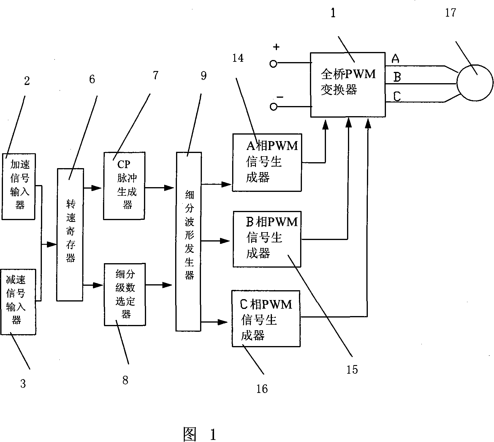
[0007] Specific Embodiment 1: The present embodiment will be specifically described below with reference to FIG. 1 . This embodiment consists of a full-bridge PWM converter 1, an acceleration signal input device 2, a deceleration signal input device 3, a rotational speed register 6, a CP pulse generator 7, a subdivision series selector 8, a subdivision waveform generator 9, and a Phase PWM signal generator 14, B phase PWM signal generator 15 and C phase PWM signal generator 16, the input end of speed register 6 connects the output end of acceleration signal input device 2 and deceleration signal input device 3 to realize by adding or subtracting Digital to select the output speed of the motor. One output end of the speed register 6 is connected to the input end of the CP pulse generator 7 to select the CP pulse frequency and output the CP pulse through the speed. The other output end of the speed register 6 is connected to the subdivision The number selector 8 selects the subd...

specific Embodiment approach 2

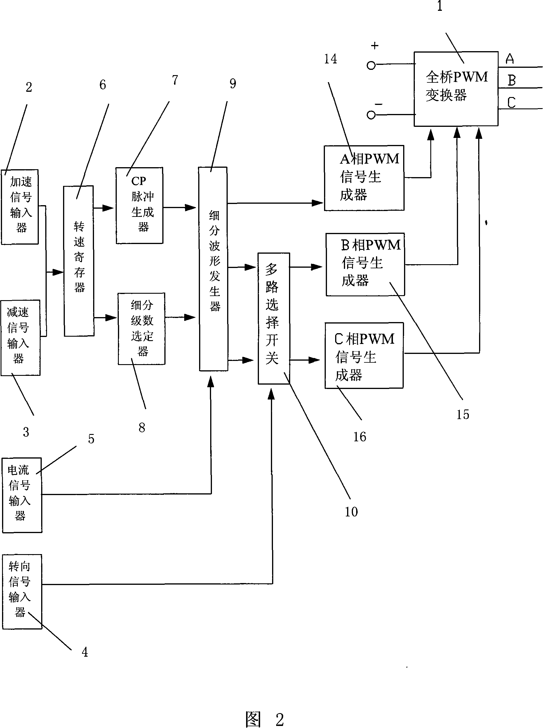
[0009] Specific Embodiment 2: The present embodiment will be specifically described below with reference to FIG. 2 . The difference between this embodiment and embodiment one is that it also includes a turn signal input device 4, a multiplexer switch 10 and a current signal input device 5, and the output end of the current signal input device 5 is connected to another subdivision waveform generator 9. The input terminal is to realize the adjustment to the motor phase current sinusoidal waveform amplitude in the subdivision waveform generator 9, and the output terminal of the steering signal input device 4 is connected to the control end of the multi-way selector switch 10, and the multi-way selector switch 10 is arranged on from the subdivision Waveform generator 9 to any two output channels on the three output channels between A-phase PWM signal generator 10, B-phase PWM signal generator 11 and C-phase PWM signal generator 12 to realize the completion of the motor by changing ...

specific Embodiment approach 3

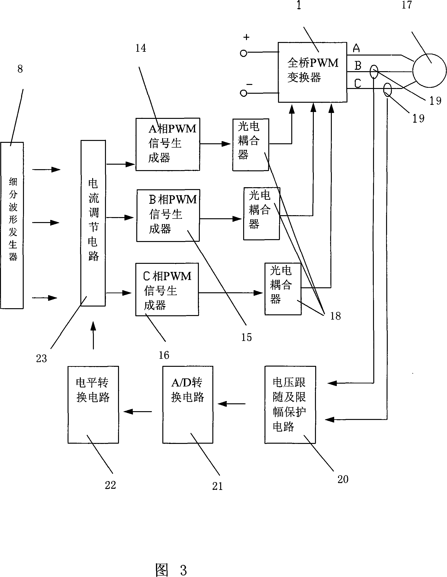
[0011] Specific Embodiment Three: The present embodiment will be specifically described below in conjunction with FIG. 3 . The difference between this embodiment and Embodiment 1 is that it also includes three photocouplers 18, and the three photocouplers 18 are respectively arranged in the A-phase PWM signal generator 14, the B-phase PWM signal generator 15 and the C-phase PWM signal generator. Between the output terminal of the generator 16 and the control terminal of the full-bridge PWM converter 1 . This embodiment electrically isolates the control circuit (low-voltage side) from the main circuit (high-voltage side), and solves the electromagnetic interference received by the control part of the stepper motor driver. The output is the main channel for the interference source to enter the system. The control system uses weak current to control strong current. When the control object is running, strong electromagnetic interference is often generated. If the output port is no...


PUM


Abstract

The present invention discloses a high-subdivision integrated stepper motor that relates to the drive machine of stepper motor. The present invention overcomes the shortages of low resolving capability of angular elongation caused by low subdivision, low frequency vibration and desynchronizing. The present invention consists of a full-bridge PWM converter, a speed acceleration signal input device, a speed reducing signal input device, a rotate speed register, a CP pulse generator, a subdivision wave generator and a PWM signal generator. The speed accelerating signal input device and the speed reducing signal input device choose rotate speed through adding and subtraction of numbers and choose the CP pulse frequency and motor through rotate speed and the subdivision grades of phasing current sinusoidal waveform, the subdivision waveform generator output each phasing current sinusoidal waveform after divided by chosen subdivision grades according to the arriving frequency of CP pulse. Then each phase of PWM signal is formed. The above control circuit is formed on the basis of FPGA and the division of the sinusoidal waveform according to time order is from 16 to 4096.

Description

technical field [0001] The invention relates to a driver for a stepping motor. Background technique [0002] At present, the control chip of the stepper motor driver uses a single-chip microcomputer or DSP. The logic unit is composed of discrete components and is controlled by software. Therefore, the reliability of the driver is not high, and there is electromagnetic interference. Anti-interference measures need to be taken, and the software program is easy to crash. Although the system can be recovered by setting a "trap", it will cause an unrecoverable failure to the transmission mechanism. In addition, limited by the operating frequency and storage capacity of the chip, the number of subdivisions of the driver is not high, generally the maximum is 256 subdivisions, so the resolution of the step angle of the stepping motor is not high, and there are low-frequency oscillations and out-of-step phenomena. There is a close relationship between the speed of the stepper motor ...

Claims


Application Information

Patent Timeline
Patent Type & Authority Applications(China)
IPC IPC(8): H02P8/22
Inventor 杨春玲朱敏李秀红
Owner HARBIN INST OF TECH
Why Eureka
Try Eureka