
Supersonic wave on-line flaw detection method and its device

A flaw detection device and ultrasonic technology, which is applied to the analysis of solids using sonic/ultrasonic/infrasonic waves, can solve the problems of heavy manual flaw detection workload, high labor intensity and high detection cost, so as to improve the speed and efficiency of flaw detection and ensure manufacturing quality. , the effect of preventing damage

Active Publication Date: 2008-02-13
CHINA ERZHONG GRP DEYANG HEAVY IND
View PDF0 Cites 24 Cited by
  • Summary
  • Abstract
  • Description
  • Claims
  • Application Information

AI Technical Summary

Problems solved by technology

[0003] At present, the ultrasonic flaw detection equipment commonly used for ultrasonic testing of large workpieces needs to be manually operated and judged by personal experience. It does not have online and real-time automatic defect detection functions, and has disadvantages such as low efficiency, high labor intensity, inconsistent subjective standards, and high testing costs.
Especially for large-scale rotating workpieces, such as gas turbine spindles, heavy containers, etc., the workpiece weighs several tons or tens of tons. Manual flaw detection requires a lot of work and low speed. Sometimes it takes several days to complete, and the quality of inspection is difficult to guarantee.

Method used


Image

  • Supersonic wave on-line flaw detection method and its device
  • Supersonic wave on-line flaw detection method and its device
  • Supersonic wave on-line flaw detection method and its device

Examples


Embodiment 1

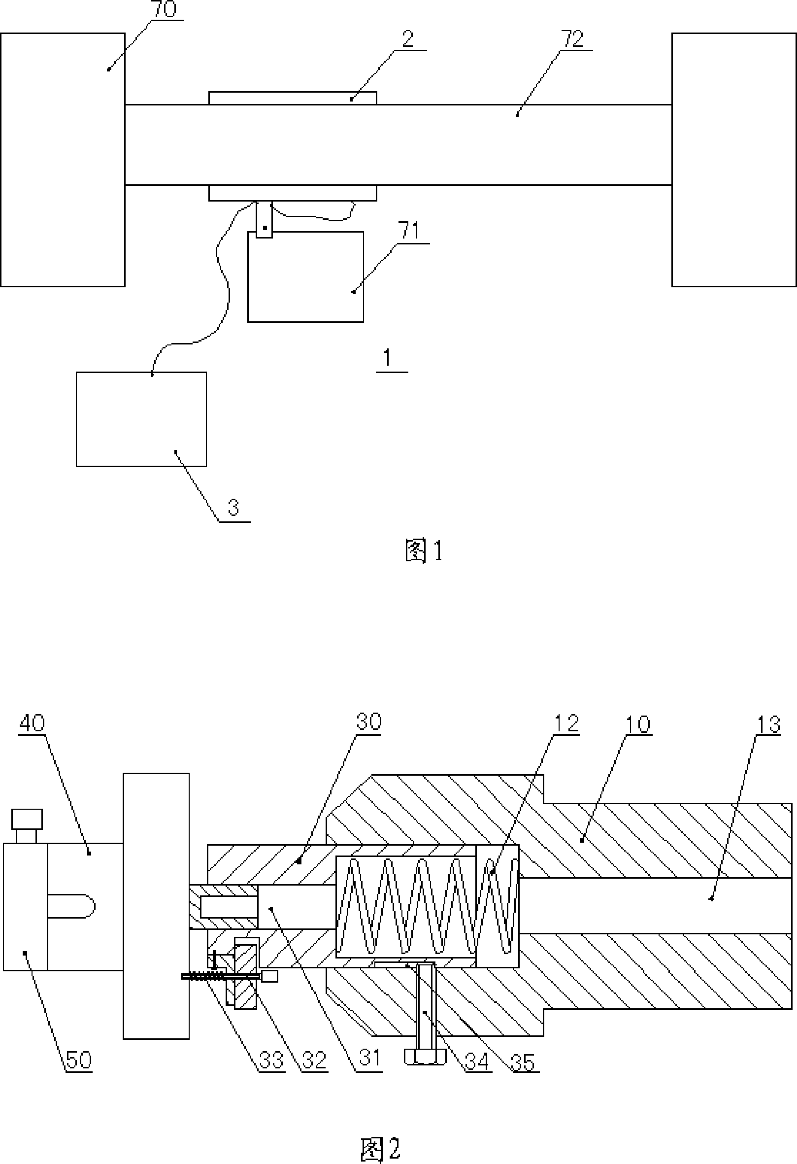
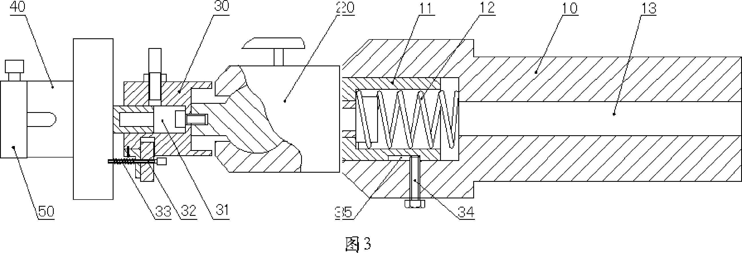
[0036] As shown in the probe device 1 shown in Figure 2, the probe base 40 is connected to the pole 10 through the connecting sleeve 30, and the anti-collision mechanism includes an axial hole opened at the front of the pole 10 and a The shock absorber 12, the connecting sleeve 30 is slidably matched with the axial guide hole, and the shock absorbing spring 12 acts axially on the connecting sleeve 30. Referring to Fig. 2 and Fig. 3, there is also a limiting structure between the connecting sleeve 30 and the pole 10 to limit the sliding distance of the connecting sleeve 30 in the axial guide hole, the limiting structure includes a limiting slot 35 and a screw 34 to limit A slot 35 is provided on the outer wall of the connecting sleeve 30 and extends axially. The screw 34 is installed on the pole 10 , and its head passes through the side wall of the axial guide hole and extends into the limiting slot 35 .

Embodiment 2

[0038] Probe device 1 as shown in Figure 3, for the probe device 1 can be installed on the lathe tool rest easily and can adjust the position of ultrasonic probe 50 flexibly, between described pole 10 and probe seat 40, be provided with multiple The degree of freedom adjustment mechanism 20 and the probe base 40 are connected to the multi-degree-of-freedom adjustment mechanism 20 through the connecting sleeve 30 . The anti-collision mechanism includes an axial guide hole opened at the front of the strut 10 and a shock absorbing spring 12 inside, as well as a sleeve 11 connected to the multi-degree-of-freedom adjustment mechanism 20, the sleeve 11 and the axial guide hole Sliding fit, the damping spring 12 acts axially on the sleeve 11 . In consideration of simplifying the structure of the probe device 1 as much as possible, the multi-degree-of-freedom adjustment mechanism 20 may preferably adopt the spherical universal joint shown in FIG. 3 .

[0039]In Embodiment 1 and Embod...


PUM


Abstract

The invention discloses an ultrasonic on-line flaw detection method and a device thereof. By using the method and the device, the on-line flaw detection can be conveniently carried out on rotating and non-rotating workpieces being processed. This comprises probe device (1), couplant supply device (2) and ultrasonic detection analyzer (3), and described probe device (1) is installed on the knife feeding mechanism (71) of processing machine tool (70), ultrasonic probe ( 50) is fixed on the probe device (1) and is opposite to the processing surface of the workpiece (72). The beneficial effect of the present invention is that ultrasonic flaw detection can be performed on workpieces in the process of processing to realize real-time online automatic detection, which can greatly improve the speed and efficiency of flaw detection of large workpieces, and is beneficial to ensure the manufacturing quality of large workpieces; the structure is simple , easy to set up, the position of the ultrasonic probe can be flexibly changed or adjusted precisely, and it can effectively prevent the ultrasonic probe from being damaged due to accidental collision.

Description

technical field [0001] The invention relates to an ultrasonic flaw detection method and its device, in particular to a method for ultrasonic on-line flaw detection of workpieces being processed, and an ultrasonic on-line flaw detection device used in the method. Background technique [0002] Ultrasonic flaw detection is the main technical method to check the internal defects of the workpiece without destroying the workpiece. The main components of large-scale power generation equipment, nuclear power plant equipment, various pipelines, bridge components, and main workpieces of large-scale equipment (such as weldments, forgings, and castings) all require ultrasonic flaw detection to ensure their manufacturing quality. Therefore, ultrasonic testing is a key technology for quality assurance in the manufacture of major national projects and various important civilian products. [0003] At present, the ultrasonic flaw detection equipment commonly used for ultrasonic testing of l...

Claims


Application Information

Patent Timeline
Patent Type & Authority Applications(China)
IPC IPC(8): G01N29/04
Inventor 陈海堤魏立民范吕慧杨蓥
Owner CHINA ERZHONG GRP DEYANG HEAVY IND
Learn More