Charging circuit for secondary battery
A backup battery and charging circuit technology, applied in the direction of secondary battery charging/discharging, battery circuit devices, circuit devices, etc., can solve the problem that the input bias voltage cannot be ignored, the detection charging current accuracy becomes low, and it is impossible to charge the backup battery and other issues to achieve the effect of shortening charging time, reducing detection errors, and increasing flexibility
- Summary
- Abstract
- Description
- Claims
- Application Information
AI Technical Summary
Problems solved by technology
Method used
Image

Examples
no. 1 example
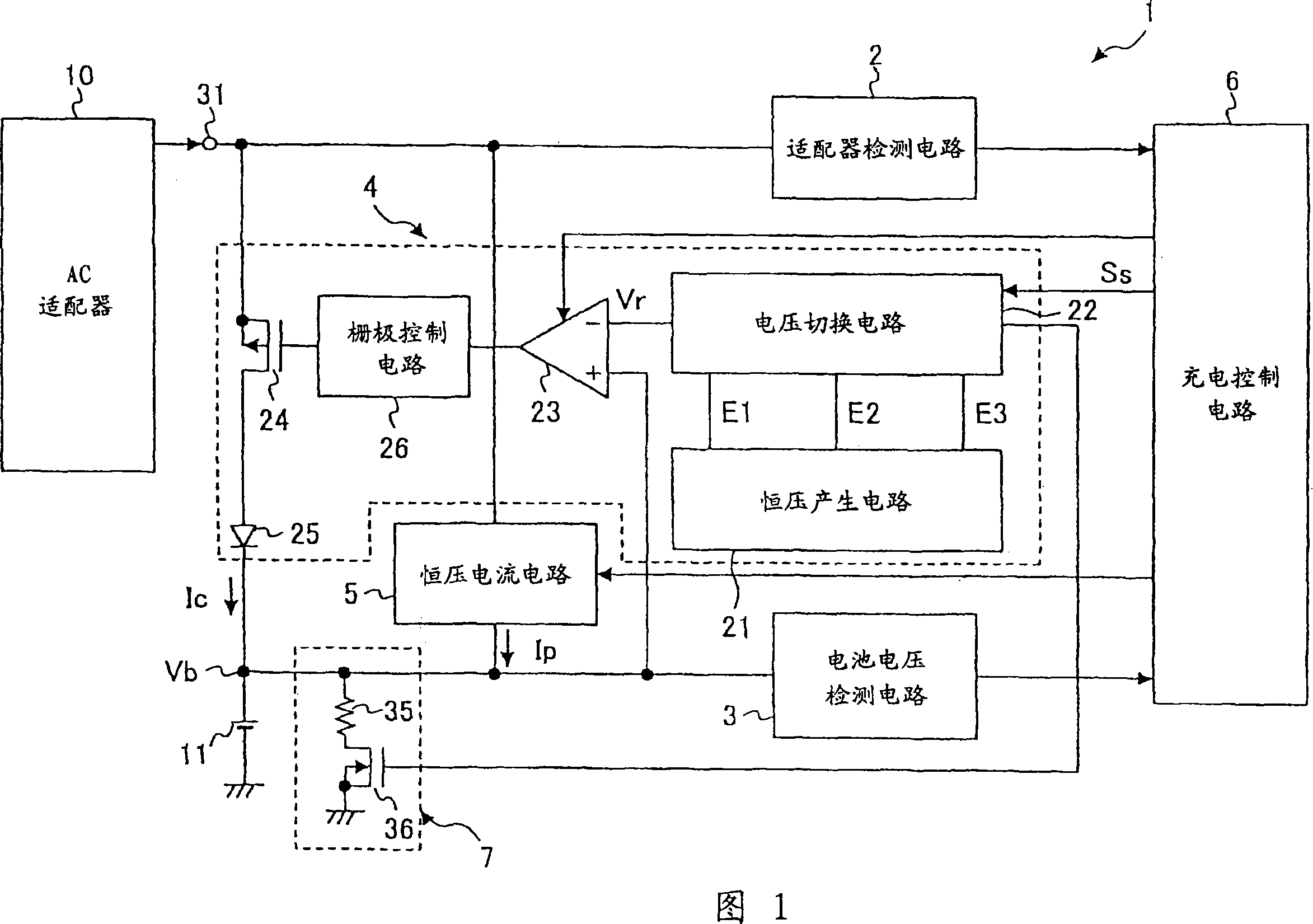
[0053] FIG. 1 shows a structural diagram of a charging circuit for a backup battery according to a first embodiment of the present invention. It should be noted that Fig. 1 shows an example of a charging circuit for a lithium-ion battery of a mobile phone.
[0054] In Fig. 1, the charging circuit 1 of the backup battery comprises: an adapter detection circuit 2 for outputting a predetermined signal when the power supply voltage from an AC adapter 10 as a DC power supply is equal to or greater than a predetermined value; a battery voltage detection circuit 3 for for detecting and outputting a positive voltage Vb (hereinafter referred to as "battery voltage") Vb of a lithium ion battery 11 used as a backup battery; and a constant voltage circuit 4 for charging the lithium ion battery 11 at a constant voltage.
[0055] In addition, the charging circuit 1 includes: a constant current circuit 5 for pre-charging the lithium-ion battery 11 with a predetermined constant current; a cha...
no. 2 example
[0083] Fig. 5 shows a charging circuit according to a second embodiment of the present invention. In Fig. 5, the charging circuit includes: AC adapter B10 for providing charging current; adapter detection circuit 12 for detecting the connection of AC adapter B10; battery voltage detection circuit 16 for detecting the voltage of backup battery 14; constant voltage The circuit 18 is used to perform constant voltage charging on the backup battery 14; the constant current circuit 20 is used to provide a constant current to the backup battery 14; the gate voltage detection circuit B22 is used to detect the voltage of the control terminal of the control transistor M1; the diode D1 , for preventing current from flowing into the AC adapter B10 from the backup battery B24; and a charge control circuit B24 for performing drive control of the constant voltage circuit 18 and the constant current circuit 20. An AC adapter B10 is connected to terminal 30 . The constant voltage circuit 18 i...
no. 3 example
[0095] FIG. 8 shows a charging circuit diagram of the backup battery 14 according to the third embodiment of the present invention. In FIG. 8, the same components as those corresponding to those in FIG. 5 are denoted by the same reference numerals, and descriptions thereof are omitted. The charging circuit according to the third embodiment includes, in addition to the charging circuit shown in FIG. 5 : a current control circuit 50 for controlling the charging current output from the pMOS transistor M1 ; and a load resistor R2 . In addition, a diode D3 is connected between the operational amplifier A1 of the constant voltage circuit 18 and the pMOS transistor M1. The current control circuit 50 includes a constant voltage generating circuit 46 , an operational amplifier A4 and a diode D2 . One end of the load resistor R2 is grounded, and the other end is connected to the gate terminal of the pMOS transistor M1.
[0096] 9A, 9B and 9B respectively show a change in the battery v...
PUM
 Abstract
Description
Claims
Application Information
 - R&D
- Intellectual Property
- Life Sciences
- Materials
- Tech Scout
- Unparalleled Data Quality
- Higher Quality Content
- 60% Fewer Hallucinations
Browse by: Latest US Patents, China's latest patents, Technical Efficacy Thesaurus, Application Domain, Technology Topic, Popular Technical Reports.
© 2025 PatSnap. All rights reserved.Legal|Privacy policy|Modern Slavery Act Transparency Statement|Sitemap|About US| Contact US: help@patsnap.com