Micro-chamber self-lubricating knife tool and preparation method thereof

A cutting tool and micro-pool technology, applied in lubricating compositions, cutting tools for lathes, manufacturing tools, etc., can solve problems such as tool wear, cutting temperature rise, and extremely severe friction conditions

Inactive Publication Date: 2008-02-20
SHANDONG UNIV
View PDF2 Cites 34 Cited by
  • Summary
  • Abstract
  • Description
  • Claims
  • Application Information

AI Technical Summary

Problems solved by technology

However, during dry cutting, due to the lack of lubrication and cooling of the cutting fluid, the friction conditions between the tool workpiece

Method used


Image

  • Micro-chamber self-lubricating knife tool and preparation method thereof

Examples


Example Embodiment

[0015] Example 1:

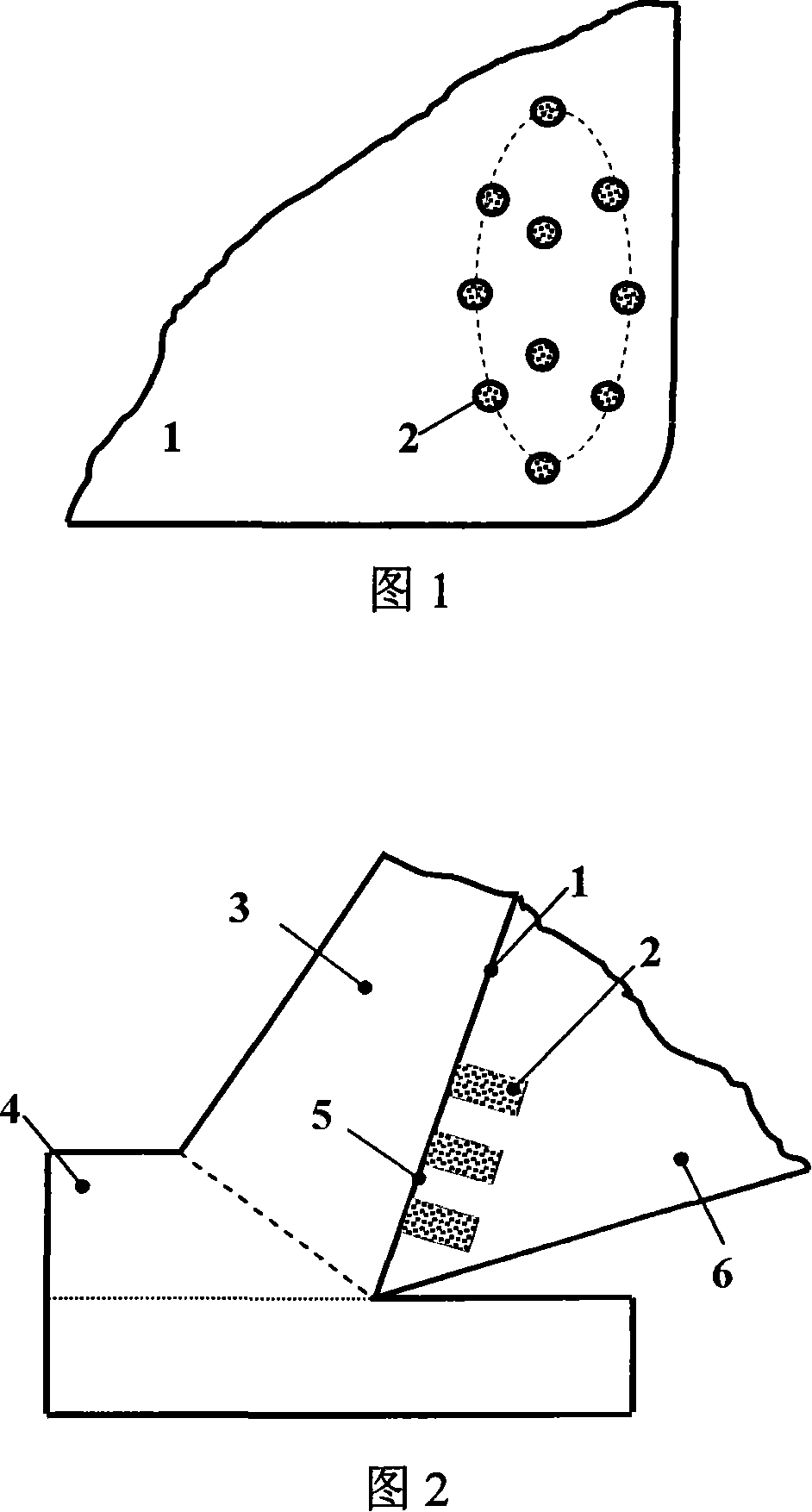
[0016] A micro-pool self-lubricating tool. The tool 6 is made of high-speed steel. The tool-chip contact area 5 of the tool rake face 1 is provided with a plurality of micro-holes 2 for storing solid lubricants. The preparation method is as follows:

[0017] 1. Using micro-EDM technology, 18 micro-holes are machined in the tool-chip contact area 5 of the rake face 1 of the high-speed steel tool. The diameter of each micro-hole is 120 μm, the depth of the micro-hole is 240 μm, and the hole spacing is 40 μm.

[0018] 2. Fill each micropore 2 with a solid lubricant powder with a diameter of 2.0μm, the type of solid lubricant is TaS 2 .

[0019] 3. When the tool is used to dry the workpiece 4, due to the high temperature of cutting, the solid lubricant in the micro-holes in the tool-chip contact area 5 softens and drags on the rake face of the tool, which will cause the tool-chip contact on the tool rake face The zone forms a continuous solid lubricating layer.

Example Embodiment

[0020] Example 2:

[0021] A micro-pool self-lubricating tool as described in Example 1, except that the tool material is cemented carbide, and the preparation method is as follows:

[0022] 1. Using micro-EDM technology, 8 micro-holes are machined in the tool-chip contact area of ​​the rake face of the cemented carbide tool. The diameter of each micro-hole is 100 μm, the depth of the micro-hole is 200 μm, and the hole spacing is 60 μm.

[0023] 2. Fill each micropore with 1.5μm diameter solid lubricant powder, the type of solid lubricant is WS 2 .

Example Embodiment

[0024] Example 3:

[0025] A micro-pool self-lubricating tool as described in Example 1, except that the tool material is ceramic, and its preparation method is as follows:

[0026] 1. Using laser processing technology, 4 micro-holes are machined in the knife-chip contact area of ​​the rake face of the ceramic tool. The diameter of each micro-hole is 60μm, the micro-hole depth is 120μm, and the hole spacing is 80μm.

[0027] 2. Fill each micropore with a solid lubricant powder with a diameter of 1.0μm, the type of solid lubricant is MoS 2 .


PUM

PropertyMeasurementUnit
Diameteraaaaaaaaaa
Depthaaaaaaaaaa
Diameteraaaaaaaaaa

Abstract

The present invention belongs to the technical filed of mechanical cutting tool production, particularly relating to a microcell automatic lubricating cutting tool and the preparation method of the cutting tool. The rack face cutting contacting area of the microcell automatic lubricating cutting tool is provided with a plurality of micro pores which are used for filling the solid lubricant. When the cutting tool is used for dry cutting, the solid lubricant inside the micro pores is softened due to the high temperature and is coated on the rack face of the cutting tool to produce the called microcell effect and to form a continual solid lubricating layer in the rack face cutting contacting area of the cutting tool, which achieves the aim of preventing sticking, reducing frication, decreasing abrasion and prolonging the use time of the cutting tool. The microcell automatic lubricating cutting tool can be widely used for dry cutting and the cutting processing of intractable material. The present invention has the advantages of overcoming the environment pollution caused by cutting fluid, achieving the clean production and decreasing the cost.

Description

technical field [0001] The invention belongs to the technical field of mechanical cutting tool manufacturing, in particular to a micro-pool self-lubricating tool and a preparation method thereof. Background technique [0002] There are always two friction pairs in the cutting process, that is, the friction pair consisting of the rake face and chips and the friction pair consisting of the flank face and the workpiece. During cutting, the rake face and flank face of the tool are constantly in contact with the chip and the workpiece and have strong friction, resulting in sharp wear of the tool, thereby reducing the tool life. At present, the main way to reduce the friction and wear of cutting tools at home and abroad is to use cutting fluid with certain lubricating effect. However, the manufacture, use and discharge of cutting fluid consume a lot of energy and resources, and cause serious pollution to the environment; and due to the increase of cutting temperature during high-...

Claims


Application Information

Patent Timeline
IPC IPC(8): B23B27/00B23B27/14B23P15/30C10M103/06C10N40/22
Inventor 邓建新
Owner SHANDONG UNIV
Why Eureka
Try Eureka