DC frequency conversion controller and its method for controlling speed of permanent magnetic synchronous electromotor rotor

A permanent magnet synchronous motor, DC frequency conversion technology, used in the control of generators, control of electromechanical brakes, control of AC motors, etc., can solve problems such as large current pulsation, loss of step, and large vibration and noise of compressors

Inactive Publication Date: 2008-02-20
SHANGHAI HITACHI ELECTRICAL APPLIANCES CO LTD
View PDF0 Cites 34 Cited by
  • Summary
  • Abstract
  • Description
  • Claims
  • Application Information

AI Technical Summary

Problems solved by technology

[0003] At present, the rectangular wave mode of "two phases being turned on at the same time" is mainly used for variable frequency drive, and the phase current waveform is approximately rectangular, resulting in abundant high-order harmonics in the main circuit and poor electromagnetic compatibility.
Moreover, when running at low frequency, the torque fluctuation is large, so the vibration and noise of the compressor running are relatively large
The current pulsation is very large when the power module of the two-phase conduction mode commutates, which is prone to out-of-step phenomenon, and in serious cases, it will cause the rotor of the DC inverter compressor to demagnetize

Method used


Image

  • DC frequency conversion controller and its method for controlling speed of permanent magnetic synchronous electromotor rotor
  • DC frequency conversion controller and its method for controlling speed of permanent magnetic synchronous electromotor rotor
  • DC frequency conversion controller and its method for controlling speed of permanent magnetic synchronous electromotor rotor

Examples


Embodiment Construction

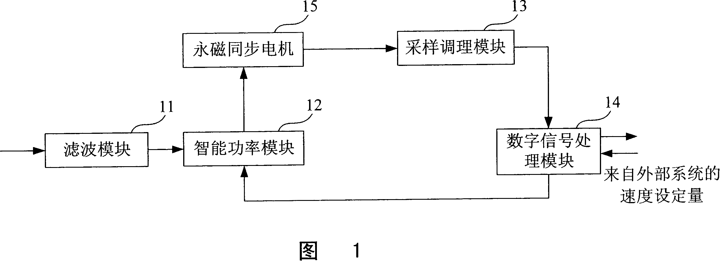
[0018] The DC variable frequency controller of the present invention includes a filter module 11, a smart power module 12 (Smart Power Module), a sampling and conditioning module 13, a digital signal processing module 14 (Digital Signal Processing, DSP for short), and a permanent magnet synchronous motor 15 (Permanent Magnet Synchronous). Motor, referred to as PMSM). Among them, the output end of the filter module 11 is connected to the input end of the intelligent power module 12 to provide power for the intelligent power module 12. The other input end of the intelligent power module 12 is DSP14, and its output end is connected to the input end of the PMSM15, the DSP module 14 The PMSM motor 15 is driven to run through the intelligent power module 12 after the proportional integral adjustment processing. The output end of the PMSM 15 is connected to the input end of the DSP 14 through the sampling and conditioning module 13, that is, the phase current when the motor is running is...


PUM


Abstract

The utility model discloses a controlling method for the rotor speed of permanent magnet synchronous electric motors, which comprises the following steps: a set speed value is provided for reference; phase current is sample; the speed and current proportional integral and sinusoidal vector pulse width can be regulated according to the set speed value and the phase current to attain the three-phase voltage signal for the operations of permanent magnet synchronous electric motors; the phase current value is restructured to drive the rotor of the permanent magnet synchronous electric motor to rotate according to the reconstructed phase voltage value; rotor position slip form observation can be carried out according to the reconstructed phase voltage value to gain the estimated position and the estimated speed of the rotor. The utility model also comprises a DC conversion controller, which in turn comprises an input device, a sampling device, two adjusting devices; speed and current proportional integral adjustment are conducted over the set speed value and the estimated speed; the two adjusting devices separately conduct the corresponding adjustment; the slip form observer generates estimated value of rotor position signal angle after dynamic compensation in accordance with the reconstructed phase voltage and the current after first conversion; a reconstructing device reconstructs the estimated value of the reconstructed the position and signal angles of the rotor to establish the estimated speed of rotors.

Description

Technical field [0001] The invention relates to a DC variable frequency controller in the technical field of automatic control and power electronics, in particular to a DC variable frequency controller based on sine wave drive and a method for controlling the rotor speed of a permanent magnet synchronous motor. Background technique [0002] Most of the existing air conditioners are controlled at a constant speed, and the cooling capacity can only be adjusted in an "on-off" manner, and the corresponding temperature fluctuations are relatively large. From the perspective of domestic and foreign development trends, highly efficient and energy-saving inverter air conditioners have gradually become the mainstream consumer. At present, frequency conversion drives are divided into two categories: AC and DC. Compared with DC frequency conversion, AC frequency conversion has the disadvantages of copper / iron loss and large eddy current loss. The DC inverter compressor mainly uses a permane...

Claims


Application Information

Patent Timeline
Patent Type & Authority Applications(China)
IPC IPC(8): H02P6/06H02P6/16F24F11/02H02P21/00H02P21/18H02P21/22H02P27/08
Inventor 李世敬汪辉穆振国
Owner SHANGHAI HITACHI ELECTRICAL APPLIANCES CO LTD
Why Eureka
Try Eureka