Nano fluid sensor based on field effect tube

A technology of field effect tube and nanofluid, which is applied in the direction of bioreactor/fermenter combination, specific-purpose bioreactor/fermenter, instrument, etc. It can solve the problems such as difficult detection of electric current, and achieve the goal of improving sensitivity and saving cost Effect

Inactive Publication Date: 2008-02-27
SOUTHEAST UNIV
View PDF0 Cites 10 Cited by
  • Summary
  • Abstract
  • Description
  • Claims
  • Application Information

AI Technical Summary

Problems solved by technology

However, when the concentration of the solution reaches 1 M, the ionic current formed is only at the nanoampere (nA) level, which requires the use of Faraday cages and other fairly sophisticated measurement equipment to detect. At present, nanochannels simulate the natural state of biomolecules. Ambient low-concentration solutions may only generate currents in the picoampere (pA) range, making currents generated by single molecules themselves more difficult to detect

Method used


Image

  • Nano fluid sensor based on field effect tube

Examples


Embodiment Construction

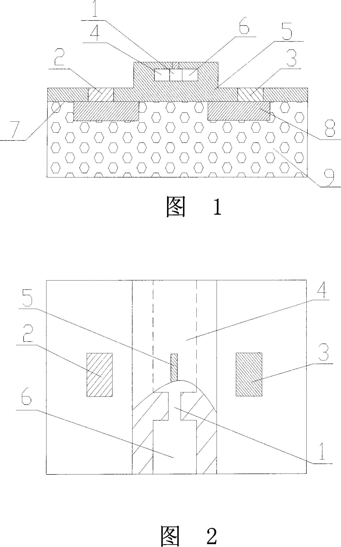
[0010] In the figure, 1, nano channel, 2, source, 3, drain, 4, left micro channel, 5, FET gate, 6, right micro channel, 7, SiO 2 Insulation layer, 8, highly doped N+ type region or highly doped P+ type region, 9, P-type thin silicon substrate or N-type thin silicon substrate.

[0011] As shown in Figure 1, a nano-channel 1, a left micro-channel 4, and a right micro-channel 6 are arranged on the field effect transistor grid 5, and the left micro-channel 4 and the right micro-channel 6 are respectively connected to the two ends of the nano-channel 1. Positive and negative electrodes are respectively added on the tube grid 5 to form a grid control loop; the resistance of the FET grid 5 control loop is composed of the resistance R of the medium in the nanochannel 1 and the resistance R of the medium in the left micron channel 4 and the right micron channel 6 Resistance R 1 , R 2 Composed in series. The resistance R of the medium in nanochannel 1 is composed of SiO 2 The surfac...


PUM


Abstract

The invention relates to a nanometer flow sensor based on the field effect tube in particular to a nanometer flow sensor which can magnify the microscopic variations of conductivity of medium into the drain current fluctuation of the field effect tube. The invention comprises the field effect tube grid, wherein the nanometer channel is arranged on the field effect tube grid, two sides of the nanometer channel are connected with left and right micrometer channel, the grid control circuit comprises the medium in the micrometer channel, the medium in the nanometer channel and positive-negative electrode, and the electric resistance of the grid control circuit comprises the electric resistance R of medium in the nanometer channel and two electric resistances R1, R2 of medium in the micrometer channel. The aim of the invention is to provide a high fidelity nanometer flow sensor based on the field effect tube which can magnify the microscopic variations of conductivity of medium into the drain current fluctuation of the field effect tube.

Description

technical field [0001] The invention relates to a nanofluid sensor, in particular to a nanofluid sensor capable of amplifying the slight change in the conductivity of a medium in a nanochannel to the fluctuation of the drain current of a field effect tube. Background technique [0002] At present, nanofluidic sensors use nanopore media to connect two fluid cell units, and a deflection voltage is applied along the length of the nanopore to generate an ionic current. When DNA molecules (heterogeneous media) pass through the nanopore, the blockage of DNA molecules will cause current flow. At this time, the DNA molecules in the channel can be judged by detecting the change of ionic current in the nanochannel. This prototype device for detecting ionic current can be used for DNA sequencing and drug screening. However, when the concentration of the solution reaches 1 M, the ionic current formed is only at the nanoampere (nA) level, which requires the use of Faraday cages and other...

Claims


Application Information

Patent Timeline
IPC IPC(8): C12M1/34C12Q1/68G01N27/00
CPCG01N33/48721
Inventor 陈云飞葛艳艳王玉娟杨决宽仲武陈敏
Owner SOUTHEAST UNIV
Why Eureka
Try Eureka