
Laser processing method and corresponding laser machining apparatus

A laser processing method and laser processing technology, applied in the TFT field, can solve problems such as cracking and reducing the bending strength of glass materials, and achieve the effects of improving temperature differences, avoiding micro cracks, and reducing thermal expansion differences

Inactive Publication Date: 2008-03-05
FOXSEMICON INTEGRATED TECHNOLOGY (SHANGHAI) INC +1
View PDF0 Cites 9 Cited by
  • Summary
  • Abstract
  • Description
  • Claims
  • Application Information

AI Technical Summary

Problems solved by technology

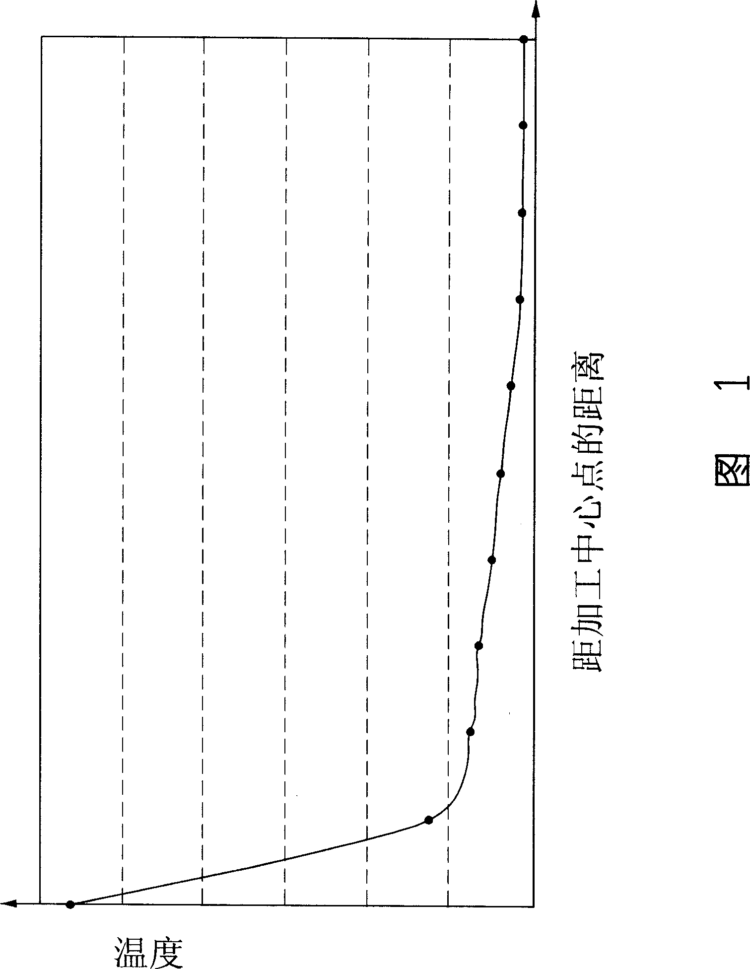
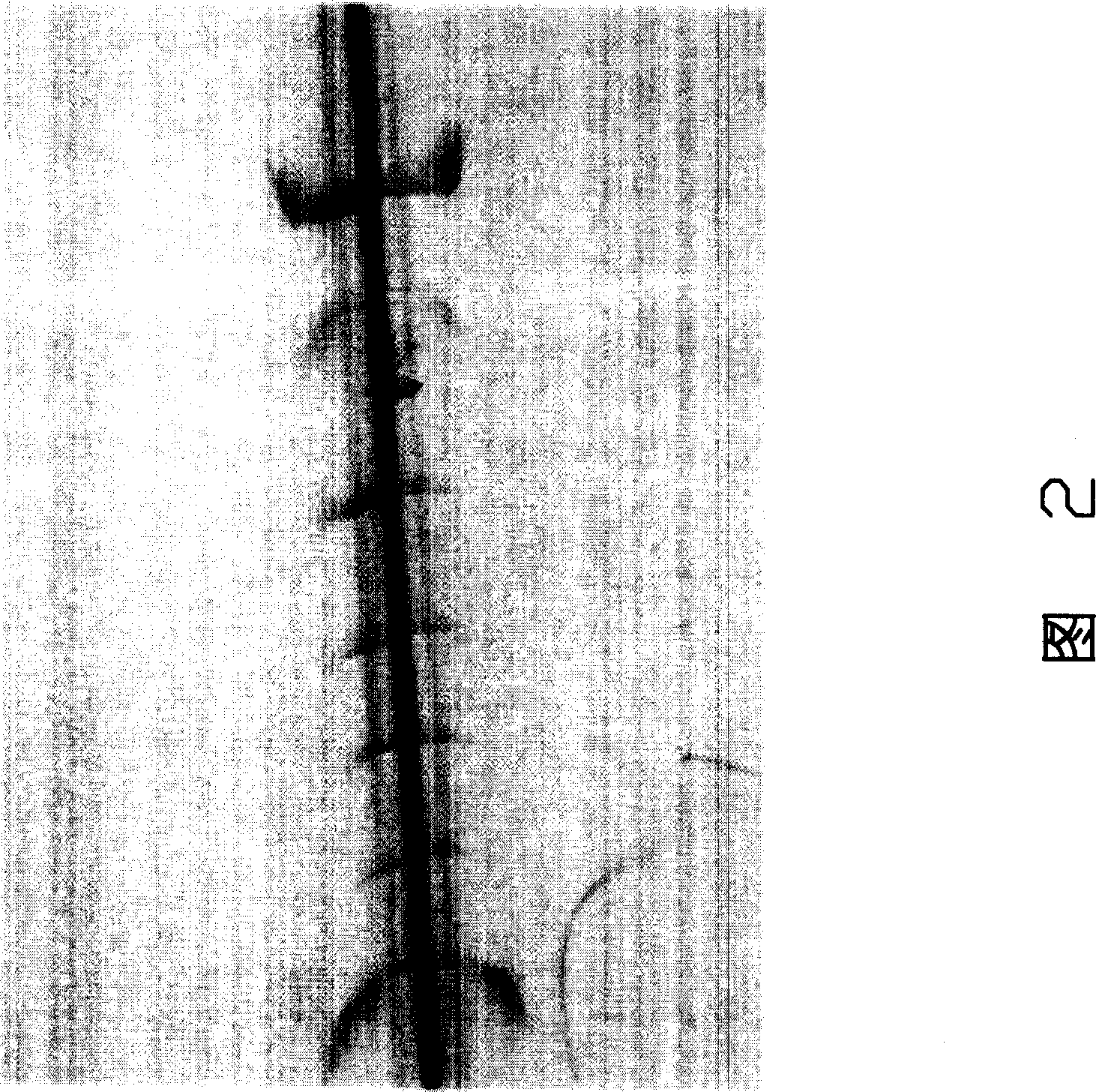
These tiny cracks create stress concentrations that reduce the flexural strength of the glass material and make the material prone to breakage during transportation

Method used


Image

  • Laser processing method and corresponding laser machining apparatus
  • Laser processing method and corresponding laser machining apparatus
  • Laser processing method and corresponding laser machining apparatus

Examples


Embodiment Construction

[0018] Embodiments of the present invention will be described in further detail below in conjunction with the accompanying drawings.

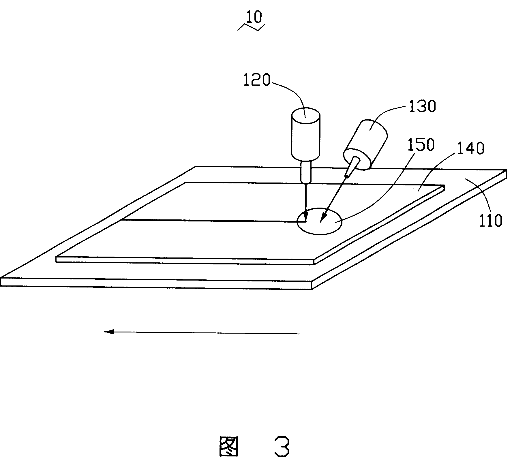
[0019] Please refer to FIG. 1 , a laser processing method provided by an embodiment of the present invention. The laser processing method comprises the following steps:

[0020] Step 1: Provide a processed object 140 and place the processed object 140 on a processing table 110 .

[0021] The processed object 140 is a brittle material, such as glass, silica or ceramics. The outer shape of the processed object 140 is preferably plate-like.

[0022] The processing table 110 is used to carry the processed object 140, which can be made of metal and other materials.

[0023] Step 2: heating the pre-processing area 150 of the processed object 140 to a predetermined temperature.

[0024] A heating source 130 is used to heat the pre-processing area 150 of the workpiece 140 to form a temperature field in the pre-processing area 150 and its vicinity. ...


PUM


Abstract

The present invention relates to laser machining process and equipment. The laser machining process includes the following steps; setting the workpiece onto the working bench, heating the machined area of the workpiece to preset temperature, and machining the heated machined area with laser beam. The laser machining equipment includes one working bench for bearing the workpiece, one laser source to emit laser beam, and one heating source to preheat the machined area of the workpiece to preset temperature and reduce the temperature difference between the temperature of the machined area and the high temperature the laser beam generates.

Description

technical field [0001] The invention relates to a laser processing method, in particular to a processing method for brittle materials such as liquid crystal display (TFT-LCD) (Thin Film Transistor, TFT for short; Liquid Crystal Display, LCD for short) glass panel. Background technique [0002] With the continuous development of display technology, liquid crystal display devices (TFT-LCD) have been widely used in consumer fields due to their own characteristics. It is regarded as a strong opponent to replace the traditional cathode ray tube (Cathode Ray Tube, CRT for short) display device. [0003] A liquid crystal display device is generally composed of two glass substrates, liquid crystal contained in the two glass substrates and a number of circuits. The liquid crystal can change the arrangement mode under the influence of the electric field to complete the display operation. In order to form liquid crystal display panels of different sizes, it is generally necessary to ...

Claims


Application Information

Patent Timeline
Patent Type & Authority Applications(China)
IPC IPC(8): B23K26/00B23K26/42B23K26/08
CPCB23K26/421B23K26/0869B23K26/083C03B33/091B23K26/4075B23K2201/40B23K26/40B23K26/60B23K2101/40B23K2103/50
Inventor 傅承祖黄俊凯陈献堂方瑞文郭访璇许宗富
Owner FOXSEMICON INTEGRATED TECHNOLOGY (SHANGHAI) INC
Learn More