
Hydraulic press constant power control structure and controlling means thereof

A technology of constant power control and hydraulic press, applied in the field of hydraulic press, can solve the problem of wasting motor power, etc., and achieve the effect of saving motor cost, saving energy and good control effect

Inactive Publication Date: 2008-03-05
TIANJIN TIANDUAN PRESS CO LTD
View PDF0 Cites 4 Cited by
  • Summary
  • Abstract
  • Description
  • Claims
  • Application Information

AI Technical Summary

Problems solved by technology

However, the selection of the main pump motor according to this formula will waste the power of the motor virtually.

Method used


Image

  • Hydraulic press constant power control structure and controlling means thereof
  • Hydraulic press constant power control structure and controlling means thereof
  • Hydraulic press constant power control structure and controlling means thereof

Examples


Embodiment Construction

[0016] In order to further understand the invention content, characteristics and effects of the present invention, the following examples are given, and detailed descriptions are as follows in conjunction with the accompanying drawings:

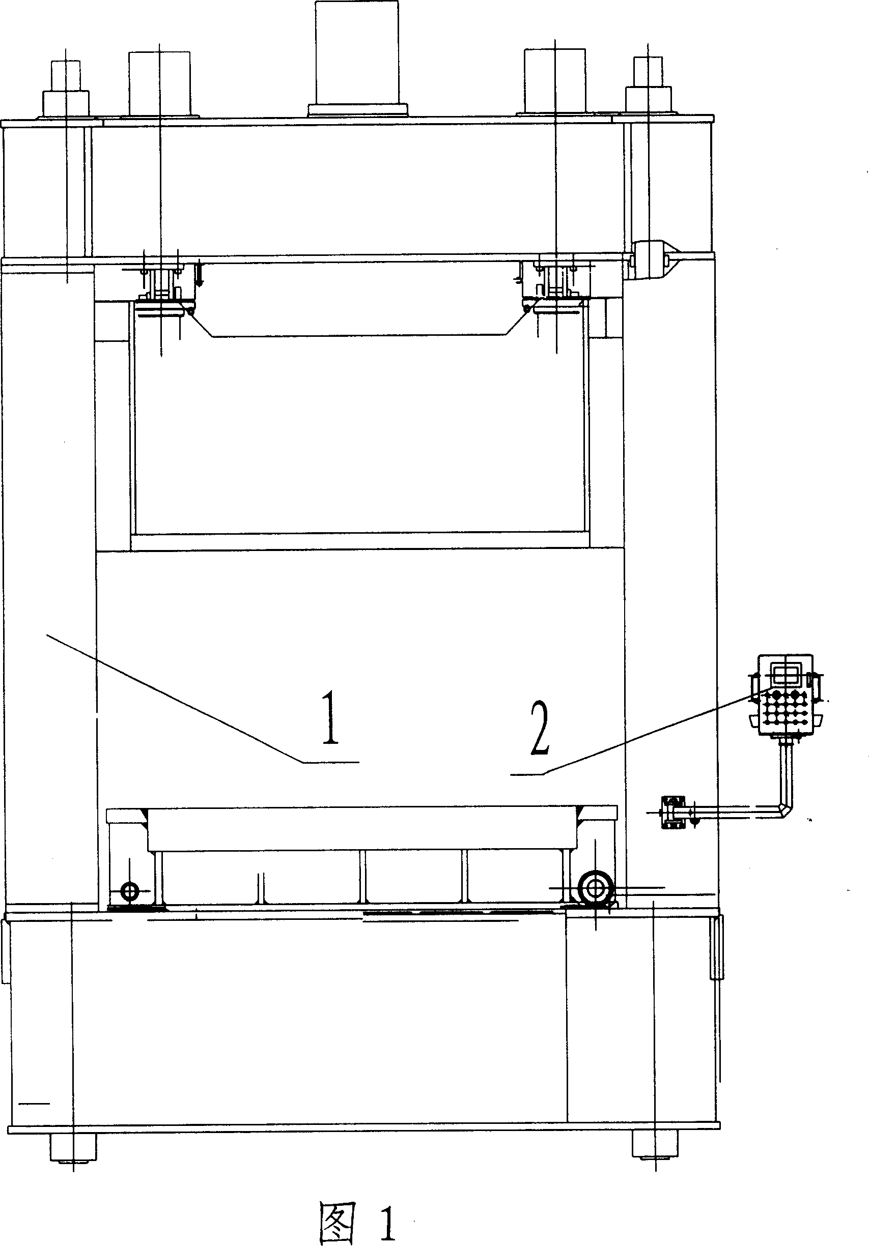
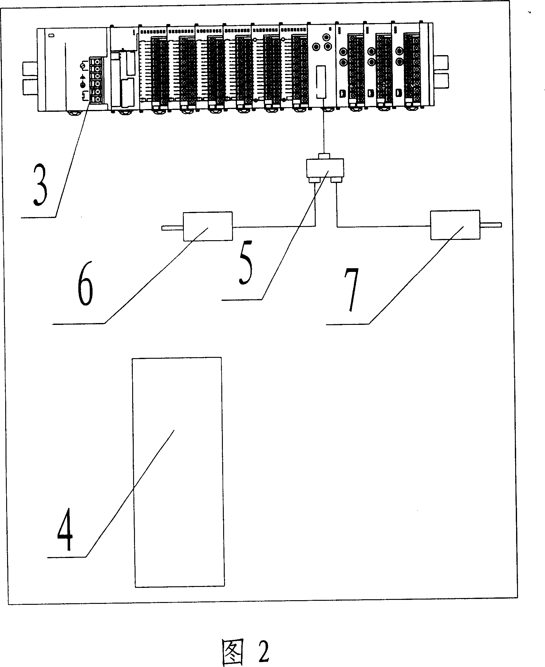
[0017] As shown in Figure 1 and Figure 2, the constant power control structure of the hydraulic press includes a PLC (programmable logic controller) 3 set in the control system of the hydraulic press for controlling the hydraulic press 1, and a rotatable operation box set on the hydraulic press 1 2 (a touch screen with a programmable control terminal is arranged on it), a splitter 5 connected to a PLC (programmable controller) 3, a slider rotary encoder 6 and a hydraulic cushion rotary encoder 7 branched out from the splitter 5, A proportional amplification board 4 is also provided on the hydraulic machine 1 .

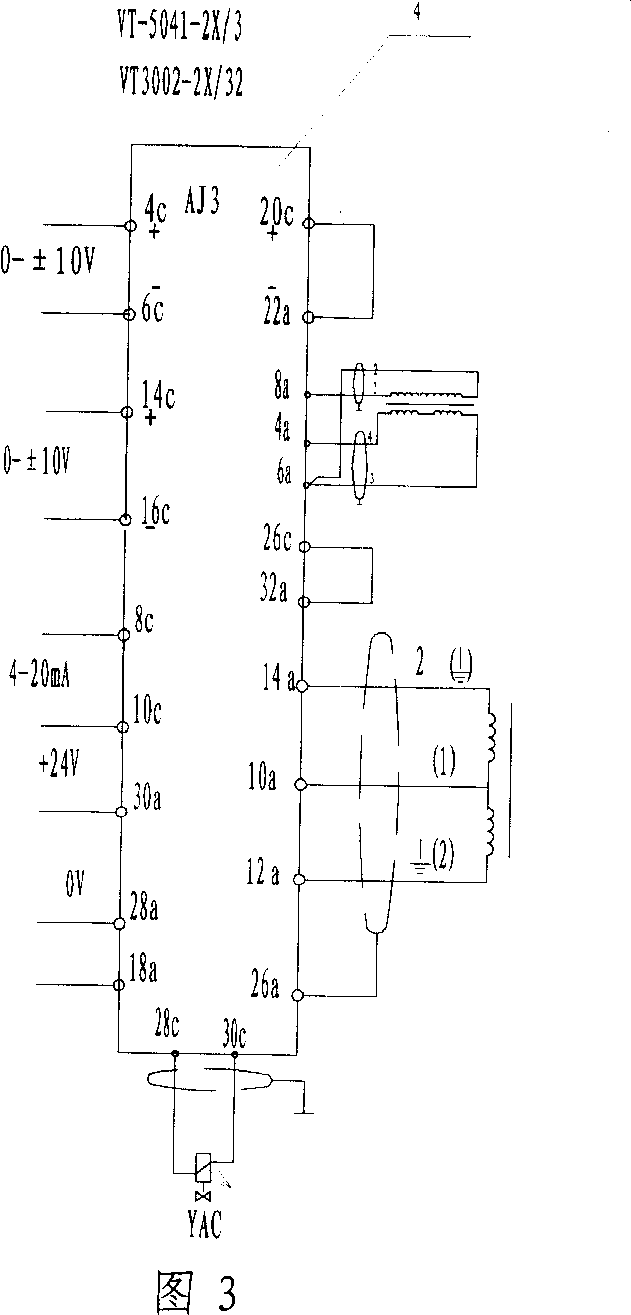
[0018] As shown in FIG. 3 , the model of the proportional amplification board 4 is VT-5041-2X / 3, and the model of its bracket is VT3...


PUM


Abstract

The present invention is one kind of constant power control structure for hydraulic press and its control process. The constant power control structure consists of one PLC, one turnable operation box, one branching unit, one slide block rotating coder, one hydraulic cushion rotating coder, and one proportional amplifier board. The proportional amplifier board is connected to one DC power source, one proportional electromagnet, one valve core displacement sensor and one swing angle sensor of the tilting mechanism. The constant power control process includes: calculating the power, regulating the voltage to obtain the calculated power and transmitting the voltage to the PLC via the RS232 port, and applying the voltage to the motor with the PLC. The present invention has low cost, saving in energy, good hydraulic press controlling effect and stable and reliable operation.

Description

technical field [0001] The invention belongs to the field of hydraulic machines, and in particular relates to a hydraulic machine constant power control structure and a control method thereof which can change pressure and flow rate under the premise of constant power and avoid motor power waste. Background technique [0002] At present, with the rapid development of the forging industry, the technical performance of the press is required to be higher and higher, and the application of constant power control technology is born. [0003] Usually, in order to meet the requirements of speed and pressure, etc., we choose the main pump motor according to the formula: Pmax=Pmax×Qmax / 612, among them, the maximum power of the first Pmax; the maximum pressure of the second Pmax ; Qmax maximum flow. However, selecting the main pump motor according to this formula will waste the power of the motor virtually. Contents of the invention [0004] In order to solve the technical problems...

Claims


Application Information

Patent Timeline
IPC IPC(8): B30B15/16
Inventor 李利清
Owner TIANJIN TIANDUAN PRESS CO LTD
Learn More