Mine ventilation mash gas burning and heat energy using device

A mine ventilation and combustion device technology, which is applied in the direction of using various fuel combustion, combustion methods, combustion types, etc., can solve the problems of unstable combustion inside porous media, complex equipment structure and operation, and difficult positioning of porous media, etc., to achieve improvement Effects of combustion stability and completeness, simplification of equipment and operation, and reduction of concentration limit

Inactive Publication Date: 2008-03-05
UNIV OF SCI & TECH OF CHINA
View PDF1 Cites 8 Cited by
  • Summary
  • Abstract
  • Description
  • Claims
  • Application Information

AI Technical Summary

Problems solved by technology

However, the problem existing in both is that regular airflow reversal is required; and in order to avoid a large amount of heat dissipation and maintain stable combustion, a good heat insulation layer is required around the reactor, resulting in complicated equipment structure and operation
[0004] The author's research group designed a new type of annular burner (patent application number 200710020394.7), which can solve the problems of the above two devices CFRR and TFRR. However, the author found in further research that the combustion center of the annular burner Area—porous media is difficult to locate; partitions need to be made of high-temperature-resistant materials, with complex structures and increased manufacturing costs; due to the existence of partitions, there are special requirements for the shape of porous media, which increases the difficulty of processing; and mine ventilation gas The combustion path in this structure is short, and the combustion is not easy to stabilize inside the porous medium, resulting in runaway temperature (the high temperature area drifts from the porous medium to the annular channel, and then drifts out of the burner from the annular channel) or flameout phenomenon

Method used


Image

  • Mine ventilation mash gas burning and heat energy using device
  • Mine ventilation mash gas burning and heat energy using device

Examples


Embodiment Construction

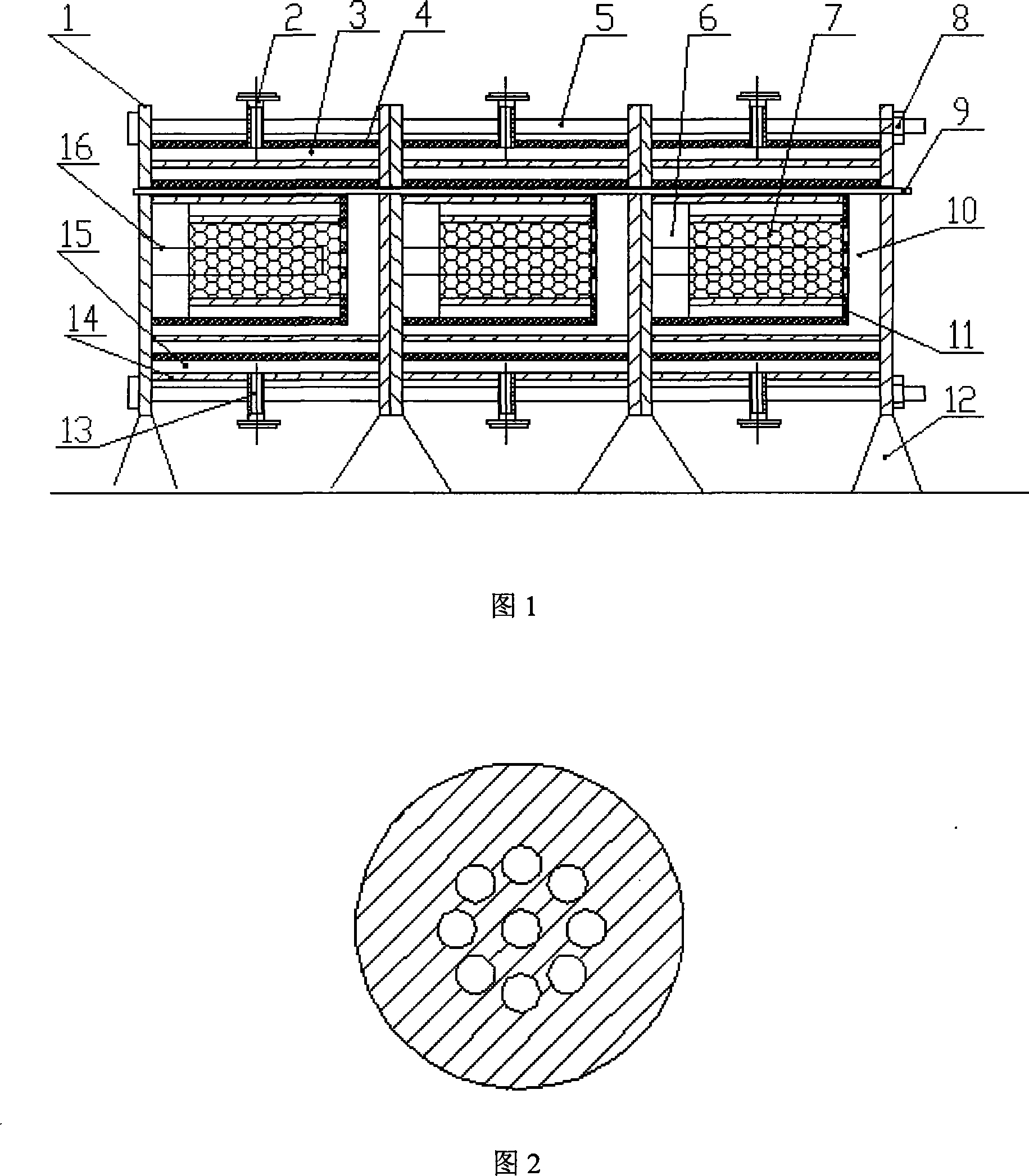
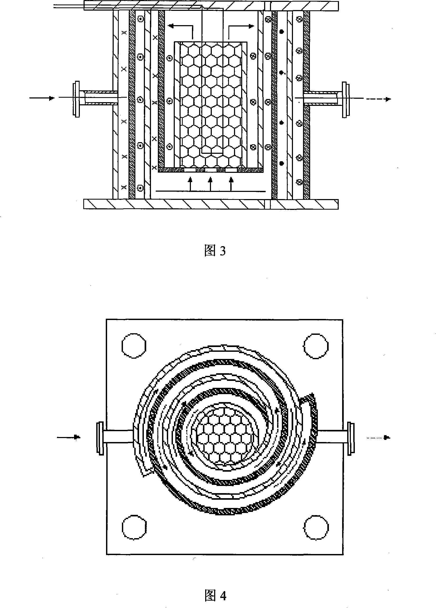
[0012] The specific implementation of a mine ventilation gas combustion and heat energy utilization device of the present invention will be further described below in conjunction with the accompanying drawings.

[0013] Fig. 1 shows a schematic structural diagram of an example of a mine ventilation gas combustion and heat energy utilization device of the present invention. A single burner has four holes on the plate 1, through which a rod 5 penetrates through the hole, and the end is fixed with a bolt 8, and a plurality of annular burners are assembled in parallel to form the device. The number of annular burners connected in parallel is determined by the maximum flow rate of mine ventilation gas in specific use. The gas inlet 13 and gas outlet 2 of the burner are respectively connected in parallel to the mine ventilation gas main pipeline and the flue gas discharge pipeline, and a solenoid valve is installed to control the number of burners used according to the real-time flo...


PUM


Abstract

This invention belongs to the thermal energy utilization device of the mine ventilation gas and includes the counter current circular channel, the centrally positioned porous material and high temperature resistant heat pipe. The mine ventilation gas is conducted circlewise to the bottom of the combustion center, rectified by the gas distribution board, and combusted axially inside the porous medium. The flume is marshaled above and conducted to the circular channel for heat exchange with the mine ventilation gas. Through parallel installation of the combustion units, the real time control of the operational number of combustor based on the mine ventilation gas flux, the control of steam flux and electrical heating components in the high temperature heat pipe based on the temperature of the combusting area, this invention meets the requirement of mine ventilation gas processing on the flux and concentration, and ensures the stable operation of the devices.

Description

Technical field: [0001] The invention belongs to the technical field of combustion equipment, in particular to a combustion device for mine ventilation gas and low-concentration gaseous hydrocarbons. Background technique: [0002] Coalbed methane is a kind of unconventional natural gas that is self-generated and self-storage in the process of coal-forming coal-forming substances mainly composed of humic organic substances in coal-bearing rock formations. It is commonly known as gas, and its main component is methane, accounting for more than 90%. Coalbed methane has always been regarded as a harmful gas that poses a serious safety threat to coal mining. In the history of coal mining, many gas, coal dust explosion accidents and coal and gas outburst accidents have been caused by mine ventilation gas. Moreover, methane, as the main component of mine ventilation gas, has a calorific value of 3.43-3.71MJ / Nm3 at room temperature, and its calorific value is equivalent to that of n...

Claims


Application Information

Patent Timeline
Patent Type & Authority Applications(China)
IPC IPC(8): F23C5/08F23G7/06
Inventor 马培勇林其钊俞瑜扈鹏飞
Owner UNIV OF SCI & TECH OF CHINA
Why Eureka
Try Eureka