Laser scattering detecting system of optical flat surface blemishes

An optical plane and laser scattering technology, which is applied in the field of optical planes, can solve problems such as beam quality degradation, failure to meet requirements, and damage to optical components, to achieve accurate and stable detection, improve resolution and accuracy, and improve signal-to-noise ratio.

Inactive Publication Date: 2008-03-05
SHANGHAI INST OF OPTICS & FINE MECHANICS CHINESE ACAD OF SCI
View PDF0 Cites 34 Cited by
  • Summary
  • Abstract
  • Description
  • Claims
  • Application Information

AI Technical Summary

Problems solved by technology

[0003] ① Beam quality declines;
[0004] ②The local thermal effect generated by the damage point causes the damage of the optical element;
[0005] ③Due to the diffraction of the beam at the damage point, damage to other optical components, etc.
The method of visual inspection alone can no longer meet the requirements

Method used


Image

  • Laser scattering detecting system of optical flat surface blemishes
  • Laser scattering detecting system of optical flat surface blemishes

Examples


Embodiment Construction

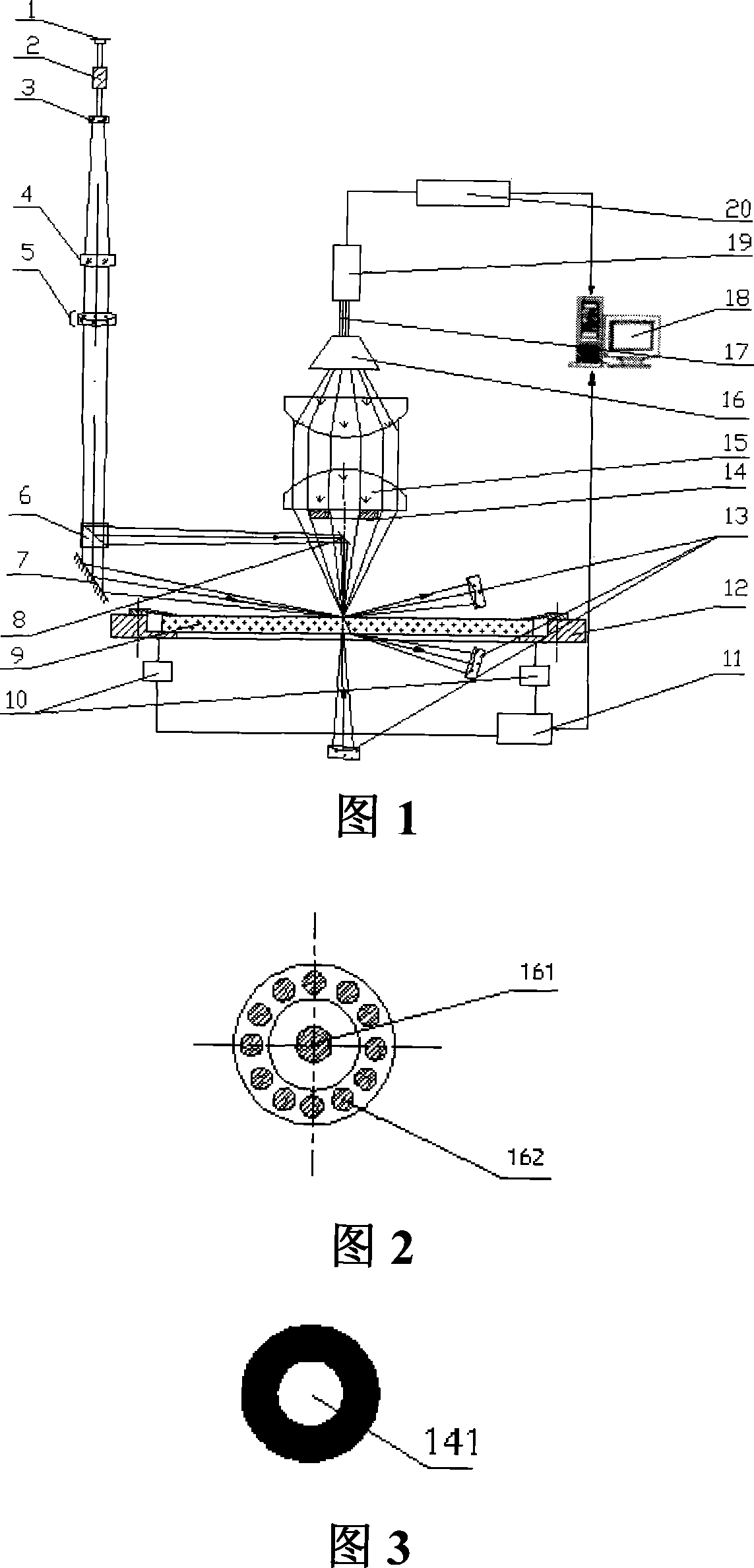
[0031] Please refer to FIG. 1 first. FIG. 1 is a schematic diagram of the principle of the laser light scattering detection system for optical flat surface defects of the present invention. It is also a structural schematic diagram of the preferred embodiment of the present invention. It can be seen from the figure that the laser scattering detection system of the optical plane surface defect of the present invention comprises:

[0032] An X-Y precision stepping platform 12 for placing the optical element 9 to be tested;

[0033] In the normal direction of the X-Y precision stepping platform 12 and above the optical element 9 to be measured, a second plane reflector 8, a scattered light collecting diaphragm 14, and a scattered light collecting objective lens are sequentially arranged on the same optical axis from bottom to top 15. An optical fiber group collector 16, which is located at the rear focal plane of the scattered light collecting objective lens 15, and the multi-cha...


PUM

PropertyMeasurementUnit
angleaaaaaaaaaa

Abstract

The system comprises: a X-Y precise stepping platform used for placing the optical component under test; using two laser beams to illuminate the surface of the optical component from both vertical and inclined directions; the generated scattered lights are collected by multi photoelectric detectors from different azimuth angles; converting the collected scattered lights into the electrical signals which are inputted into the computer; the computer controls the X-Y precise stepping platform to drive the optical component under test; making scan measurement, and comparing the scattered light signals with the scattered light signals used for showing the faults on the optical flat surface in order to realizing the location, classification and level of the faults on the optical flat surface.

Description

technical field [0001] The invention relates to an optical plane, in particular to a laser light scattering detection system for optical plane surface defects. The system uses the scattering of incident laser light by defects on the surface of the optical plane, and uses the principle of Mie scattering to collect scattered light in various directions of defects in multiple channels under dark field conditions, so as to realize the identification, positioning, classification and classification of defects. Background technique [0002] The so-called surface defect refers to the unusual structure on the surface of optical components. The surface defects of precision optical components are roughly divided into pits, scratches, open bubbles, broken points and broken edges, which are important indicators of optical processing quality. The impact of defects The main manifestations are: [0003] ① Beam quality declines; [0004] ②The local thermal effect generated by the damage po...

Claims


Application Information

Patent Timeline
Patent Type & Authority Applications(China)
IPC IPC(8): G01N21/958G01N21/49
Inventor 程兆谷覃兆宇张志平黄惠杰钱红斌朱健强
Owner SHANGHAI INST OF OPTICS & FINE MECHANICS CHINESE ACAD OF SCI
Why Eureka
Try Eureka