Periodic time dynamic magnetized light-magnetic-synchro magneto-optic test method

A technology of dynamic magnetization and testing methods, which is applied in the direction of magnetic susceptibility measurement and magnetic performance measurement, and can solve the problems that limit the extensive development of dynamic magnetization performance research.

Inactive Publication Date: 2008-03-12
SUN YAT SEN UNIV
View PDF0 Cites 6 Cited by
  • Summary
  • Abstract
  • Description
  • Claims
  • Application Information

AI Technical Summary

Problems solved by technology

It is difficult to meet the experimental conditions such as high-frequency strong magnetic field and broadband amplification technology in the macro-scale space, which limits the extensive development of dynamic magnetization performance research

Method used


Image

  • Periodic time dynamic magnetized light-magnetic-synchro magneto-optic test method
  • Periodic time dynamic magnetized light-magnetic-synchro magneto-optic test method
  • Periodic time dynamic magnetized light-magnetic-synchro magneto-optic test method

Examples


example 1

[0014] Example 1 Dynamic hysteresis loop measurement

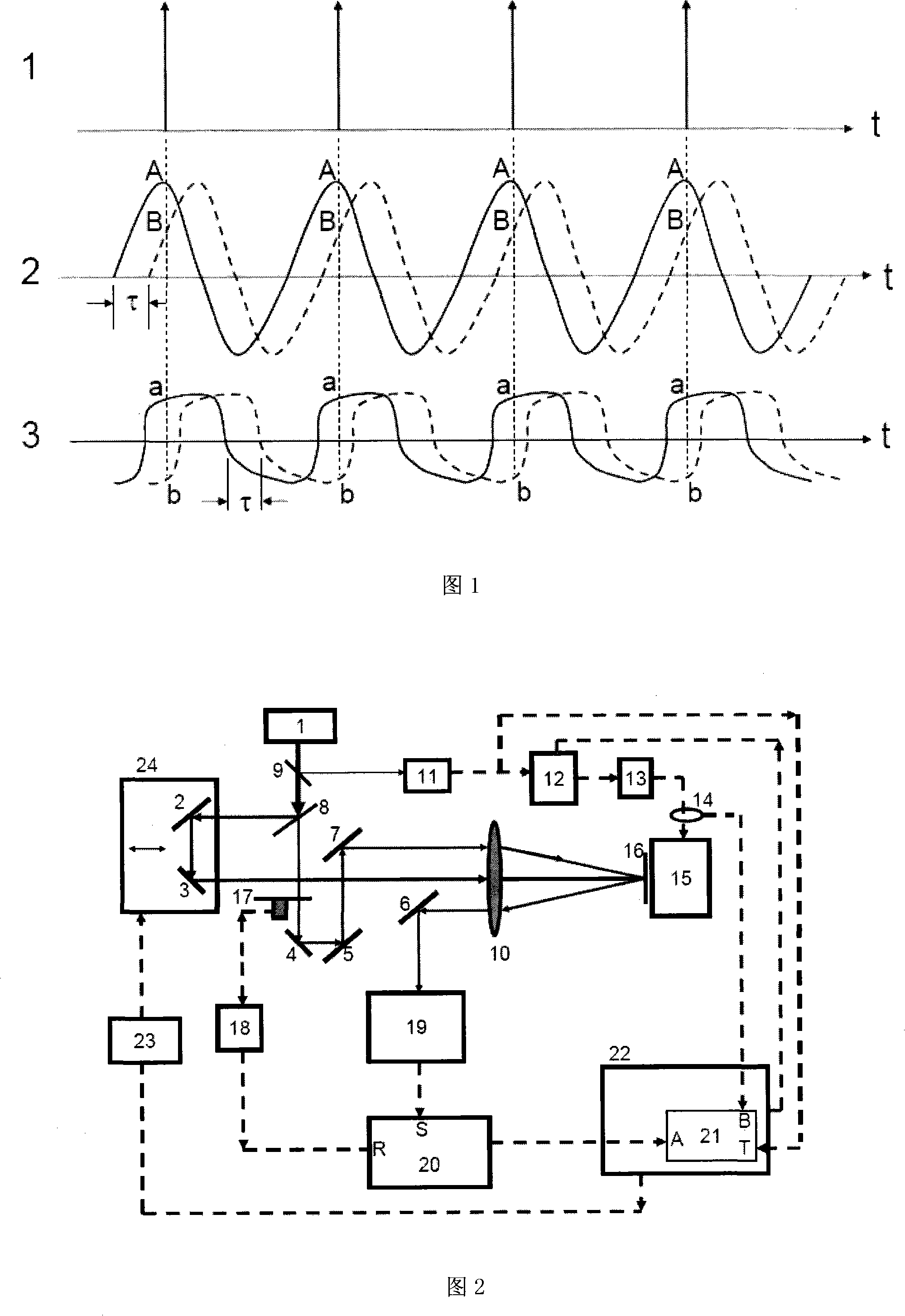
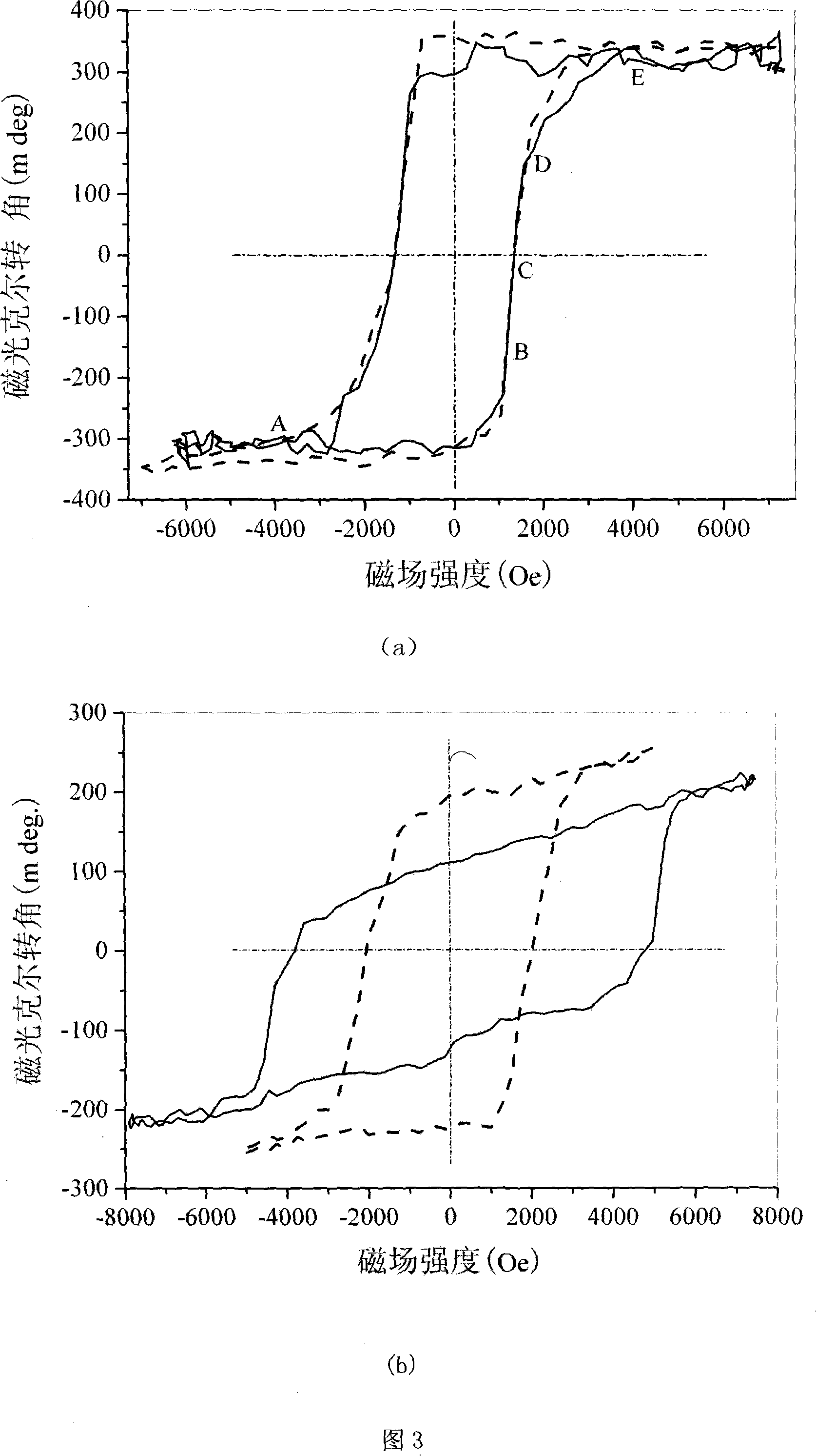
[0015] The variation of hysteresis loop with frequency is one of the important means to study the dynamic magnetization characteristics of magnetic materials. This example tests the dynamic hysteresis loops of TbCo and TbFeCo thin films to show the beneficial effect of the testing method of the present invention. In the experimental scheme in Fig. 2, the "pump light" is blocked, and only the "probe light" is irradiated on the sample, and returns to the "light polarization meter (19)". Under computer control, the time delay amount of the scanning time delay device (12) changes one cycle, and the scanning step distance is set to 5 μs; the A / D card (21) triggers externally synchronously from the laser synchronous electric pulse of the PIN diode (11) Next, the changes of the magneto-optical Kerr rotation angle and the alternating driving current of the magnetic field generator with the delay time are collected synchronously t...

example 2

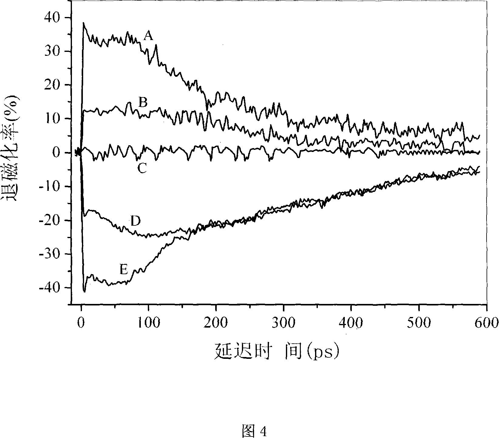
[0016]Example 2 Magnetic Bias Field Dependent Measurement of Ultrafast Demagnetization Kinetic Process

[0017] The current theory of ferromagnetism holds that magnetism originates from the exchange of unoccupied electrons in the outer orbits of adjacent atoms. Then, if you change the distribution of electrons in the outer shell, you should be able to observe a change in magnetism. Based on this idea and the development of femtosecond laser technology, a method for studying ultrafast demagnetization kinetics based on femtosecond laser pump-probe technology has been developed internationally. Using "pump light" to excite the magnetic sample, the exchange-coupled electrons are excited to a high-energy state, causing the demagnetization of the sample, but the excited electrons are unstable and will gradually return to their original initial state. The process from electron excitation to recovery is called demagnetization kinetics. The demagnetization kinetics usually occur on a...


PUM


Abstract

A cyclic dynamic magnetizing optomagnetic synchronous magnetic light testing method synchronously imposes a linear polarization cyclic laser narrow pulse train and a cyclic alternating magnetic field to a magnetic sample. The cyclic alternating magnetic field realizes cyclic and dynamic magnetization of the magnetic sample. After the cyclic laser narrow pulse train reacts with the magnetic sample, polarization of transparent lights or reflected lights of the pulse train will change to measure magnetization variation of the magnetic sample. In addition, the cyclic laser pulse train synchronously triggers a time delayer to output a time delay of the same frequency and time to adjust a synchronous trigger cyclic alternating magnetic field with adjustable electric pulse train. Thus, the laser pulse reacting with the sample repeatedly measures a same magnetization stable in the cyclic alternating magnetization of the sample and converts the measuring in the dynamic magnetization into static measuring according to a principle specified in the attached figure 1. Scanning time delay realizes to measure a magnetizing period. The measuring sample discloses benefit and application of the present invention to magnetic deflection in ultra-fast demagnetization dynamics test.

Description

technical field [0001] The invention relates to a test method for periodic dynamic magnetization of magnetic materials. It is characterized by using periodic laser pulse trains to synchronize periodic alternating magnetic fields and synchronously sampling periodic dynamic magnetization of magnetic samples excited by periodic alternating magnetic fields. It is an optical-magnetic synchronous magneto-optical test method based on magneto-optical effects. Background technique [0002] Magnetic storage is the main way of modern information storage. Such as computer hard disk. In the past decade, the storage density of computer hard disks has increased thousands of times, but in stark contrast has been the slow progress in the speed of data access. The current read and write speed of hard disk data is only about 200Mbits / s, which is only several times higher than that of ten years ago. One of the reasons for the slow progress of magnetic storage is that the research on the dyna...

Claims


Application Information

Patent Timeline
Patent Type & Authority Applications(China)
IPC IPC(8): G01R33/12G01R33/16
Inventor 赖天树刘晓东陈志峰高瑞鑫
Owner SUN YAT SEN UNIV
Why Eureka
Try Eureka