
Electrophotographic photosensitive body

A technology of electrophotography and photoreceptor, used in optics, electrography, instruments, etc.

Inactive Publication Date: 2008-03-12
IDEMITSU KOSAN CO LTD
View PDF4 Cites 1 Cited by
  • Summary
  • Abstract
  • Description
  • Claims
  • Application Information

AI Technical Summary

Problems solved by technology

[0016] The inventors of the present invention have conducted intensive studies to solve the above-mentioned problems, and found that by dispersing particles having a double-layer structure in a predetermined ratio on the surface layer of the photoreceptor, the double-layer structure consists of a core material and a rubber material having a material larger than the core material. Composition of outer shell material with high hardness can obtain an electrophotographic photoreceptor that is particularly excellent in mechanical properties such as brush resistance, has electrophotographic properties such as cleaning properties, and has no problems such as light scattering and poor dispersion due to aggregation. So far, the present invention has been completed.

Method used


Image

  • Electrophotographic photosensitive body

Examples


manufacture example 1

[0213] Production Example 1 (Oil-encased melamine-formaldehyde resin microcapsules)

[0214]The pH of 100 g of a 5 mass % aqueous solution in which an ethylene-maleic anhydride copolymer (manufactured by モンサント ミカルズ, EMI-31), which is an anionic water-soluble polymer substance, was dissolved was adjusted to 4.5, and mineral oil was added to the solution. [ISOVG150, dynamic viscosity of center value 150mm 2 / s (40° C.)] 100 ml was used as a fluid, and was emulsified and dispersed with a homogenizer to obtain an O / W type emulsion with an oil droplet diameter of 2-3 μmm.

[0215] While stirring this emulsion system, 70 g of a solution of a methylol / melamine resin aqueous solution (manufactured by Sumitomo Chemical Co., Ltd., Spemire-Semi-Rejin 613) adjusted to a solid content of 17% by mass was added, and the temperature of the system was increased to At 55° C., stirring was continued for about 2 hours, and then 15% by mass of caustic soda aqueous solution was added to adjust the...

Embodiment 1

[0224] Using a polyethylene terephthalate resin film on which aluminum metal was vapor-deposited as a conductive substrate, a charge generating layer and a charge transporting layer were sequentially laminated on the surface thereof to manufacture an electrophotographic photoreceptor having a laminated photosensitive layer formed thereon.

[0225] 0.5 mass part of oxytitanium phthalocyanine was used as a charge generating substance, and 0.5 mass part of butyral resin was used as binder resin.

[0226] These were added to 19 parts by mass of dichloromethane as a solvent, dispersed with a ball mill, the dispersion was applied on the surface of the above-mentioned conductive base film with a bar coater, and dried to form a charge generating layer with a film thickness of about 0.5 μm. .

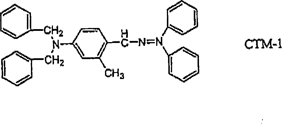
[0227] Next, 0.5 g of the compound (CTM-1) represented by the following structural formula as a charge transport material,

[0228]

[0229] and polycarbonate resin [PC-1: 1,1-bis(4-hydroxyp...

Embodiment 2

[0242] Except for replacing the polycarbonate resin (PC-1) of Example 1 with a polycarbonate resin [PC-2: 2,2-bis(3-methyl-4-hydroxyphenyl)propane polycarbonate, viscosity uniformity Except molecular weight=50000], a photoreceptor was produced in the same manner as in Example 1, and the dispersibility and electrophotographic properties were evaluated.

[0243] These results are shown in Table 1.


PUM


Abstract

Disclosed is an electrophotographic photosensitive body having a photosensitive layer on a conductive base. This electrophotographic photosensitive body is characterized in that at least the outermost layer thereof contains particles having a double structure composed of a core member and a shell member having a lager rubber hardness than the core member. This electrophotographic photosensitive body exhibits excellent mechanical strength such as wear resistance, abrasion resistance and scratch resistance as well as excellent electrophotographic characteristics such as cleaning properties for a long time.

Description

technical field [0001] The present invention relates to an electrophotographic photoreceptor, and more particularly, to an electrophotographic photoreceptor which has excellent mechanical strength and electrophotographic properties durable to repeated use for a long time and is applicable to various electrophotographic fields. Background technique [0002] Examples of electrophotographic photoreceptors that have recently been studied and utilized include electrophotographic photoreceptors in which the photosensitive layer has at least two layers, a charge generating layer (CGL) that generates charges by exposure to light, and a charge transporting layer (CTL) that transports charges. A laminated organic electrophotographic photoreceptor (OPC); a single-layer type organic electrophotographic photoreceptor in which the photosensitive layer is formed of a single layer formed by dispersing a charge generating substance and a charge transporting substance in a binder resin, Alter...

Claims


Application Information

Patent Timeline
Patent Type & Authority Applications(China)
IPC IPC(8): G03G5/147G03G5/05
CPCG03G5/14795G03G5/14791G03G5/14708G03G5/147G03G5/14704
Inventor 宫本秀幸彦坂高明
Owner IDEMITSU KOSAN CO LTD
Learn More