Eureka AIR delivers breakthrough ideas for toughest innovation challenges, trusted by R&D personnel around the world.

Volume type assembled multifunctional heat exchanger

A heat exchanger and assembly type technology is applied in the fields of showers, volumetric assembled wall-mounted gas heating, heat exchangers, and antifreeze multifunctional heat exchangers. High technical requirements, to achieve the effect of high labor intensity of workers, improved labor productivity, and clean and hygienic working environment

Inactive Publication Date: 2008-03-19
孙广福
View PDF0 Cites 2 Cited by
  • Summary
  • Abstract
  • Description
  • Claims
  • Application Information

AI Technical Summary

Problems solved by technology

But in the long-term use, it is found that since the heat exchangers are all welded by argon arc, in areas with poor water quality and after long-term use, once the heat exchangers are scaled or damaged, they must be completely replaced, and users must pay a large amount for this. Material costs and labor costs, the replaced heat exchanger has no possibility of repair and utilization, and can only be scrapped, resulting in a lot of waste
At the same time, a large amount of harmful gas will be produced during the argon arc welding process, the working environment is harsh, the labor intensity of the workers is high, the technical requirements for the workers are high, the welding cost is high, and the labor efficiency is low.

Method used


Image

  • Volume type assembled multifunctional heat exchanger

Examples


Embodiment Construction

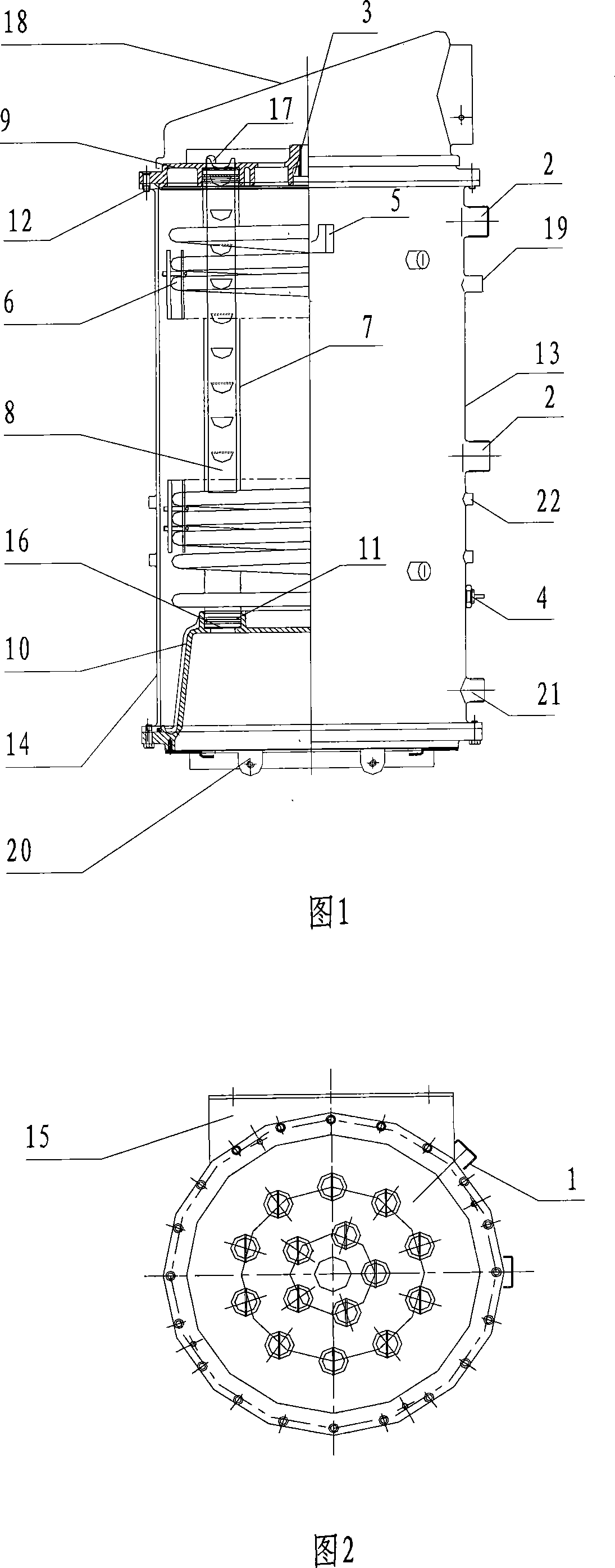
[0021] As shown in Figures 1 and 2, the present invention consists of a housing 13, an electric heater 4, a coil 6, inner and outer finned tubes 7, a spoiler 8, an upper tube plate 9, a combustion chamber 10, a fastening bracket 15, a condensation The water absorber 16, the burner fixing part 20, the emptying / replenishing water port 21, and the temperature limiter of the heating belt are composed of 22. All parts are socket-type, connected by tongue and groove, and fixed and positioned by multiple screws. The pipe fittings connected to the heater are connected to the heat exchanger through seals, and external interfaces are provided on the shell: domestic hot water thread head 1, heating thread head 2 and overflow thread head 3, and coil pipes 6 and The inner and outer ribbed tubes 7 are provided with spoilers 8; the inside and outside of the housing are provided with electric heaters 4, the lower part of the housing is provided with a combustion chamber 10, and the upper part ...


PUM


Abstract

The invention relates to a volume style assembly type multi-purpose heat interchanger, which comprises a sensor, a casing, an electric heater, a coil pipe, an inner ribbed pipe, and an outer ribbed pipe, a burbling sheet, an upper pipe plate, a combustion chamber, a fastening supporting rack, a condensed water consumption device, and a gas collector. All parts are socket joint-typed, are connected through a rabbet joint, and fastened and positioned through a plurality of threaded rods, a pipe fitting is oppositely connected with the heat interchanger through a sealing element, outer connectors of life hot water tail end, heating tail end, overflow tail end, emptying / water compensation opening and heating belt temperature limit device are arranged on the casing body, the coil pipe, the inner ribbed pipe and the outer ribbed pipe are arranged in the casing body, and the burbling sheets are arranged on the inner ribbed pipe and the outer ribbed pipe; the electric heaters are arranged on the interior part and the exterior part of the casing body, the combustion chamber is arranged at the lower part of the casing body, the upper pipe plate is arranged at the upper part of the casing body, a seal ring and the fastening supporting rack are respectively arranged at the both ends of the upper part of the casing body; the condensed water consumption devices are arranged at the lower parts of the inner ribbed pipe and the outer ribbed pipe. The invention changes the molding method of the traditional small volume type heat interchanger, and has the advantages that the installation and the maintenance are convenient, the thermal efficiency is high, and the operating cost is low, etc.

Description

technical field [0001] The invention relates to a heat exchanger, in particular to a volumetric assembled wall-mounted (floor) gas heating, shower and antifreeze multifunctional heat exchanger, which belongs to the technical field of international patent classification F28D heat exchange equipment. Background technique [0002] In my previous patent application, I once disclosed an atmospheric pressure gas-fired heating bath boiler, which solved the problem of obtaining hot water at different temperatures according to different needs; I also disclosed an internal and external tooth-shaped heat exchange tube, which increased the heat exchange area , improve thermal efficiency, and provide a gas boiler with an antifreeze electric heating device that prevents the boiler from being damaged by freezing after the gas antifreeze device fails. But in the long-term use, it is found that since the heat exchangers are all welded by argon arc, in areas with poor water quality and after ...

Claims


Application Information

Patent Timeline
IPC IPC(8): F24H1/40
Inventor 孙广福
Owner 孙广福
Why Eureka
Eureka Blog
Learn More