Radiator of electronic device

A technology of electronic devices and radiators, applied in the field of radiators, can solve problems such as liquid leakage, electronic equipment not allowed, and air cooling technology that cannot meet the cooling requirements

Inactive Publication Date: 2008-03-19
刘胜
View PDF0 Cites 23 Cited by
  • Summary
  • Abstract
  • Description
  • Claims
  • Application Information

AI Technical Summary

Problems solved by technology

It is more and more common to apply large heat flux chips in high-performance supercomputers, military avionics and other equipment, and pure air cooling technology can no longer meet the cooling requirements
Liquid cooling is widely used in high heat flux chip cooling because of its high efficien

Method used


Image

  • Radiator of electronic device
  • Radiator of electronic device
  • Radiator of electronic device

Examples


Embodiment 1

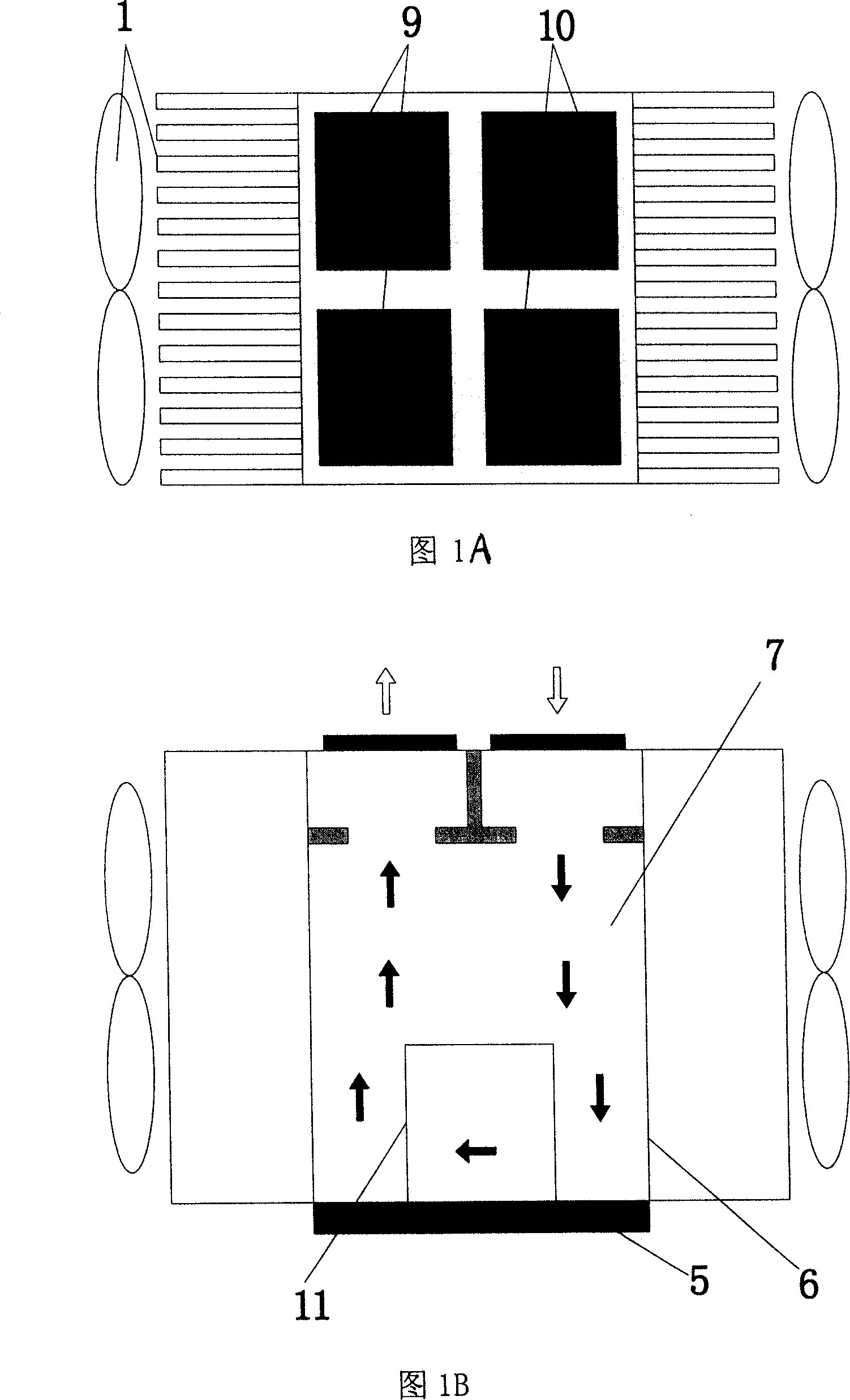
[0015] See Figure 1A, Figure 1B, the working principle of the radiator: when the piezoelectric diaphragm group 9 is energized and deformed downward, at the same time, the piezoelectric diaphragm group 10 is energized and deformed upward, and the deformation of the two piezoelectric diaphragm groups will cause the radiator The cooling liquid 7 in the shell 6 moves, and the cooling liquid 7 in contact with the heat source 5 flows quickly to other parts of the radiator after absorbing heat, and the heat carried by the heat fluid is carried out by the radiator fins 14 on the four walls and the fan 1. Heat exchange, transfer heat to the surrounding environment, the temperature of the fluid drops rapidly, when the cooled fluid returns to the bottom of the radiator shell 6, the heat sink 11 in the radiator shell 6 absorbs the heat from the heat source 5 Conducted heat, the cooled fluid reabsorbs heat and begins a new cycle.

[0016] In order to prevent the electrical input of the pie...

Embodiment 2

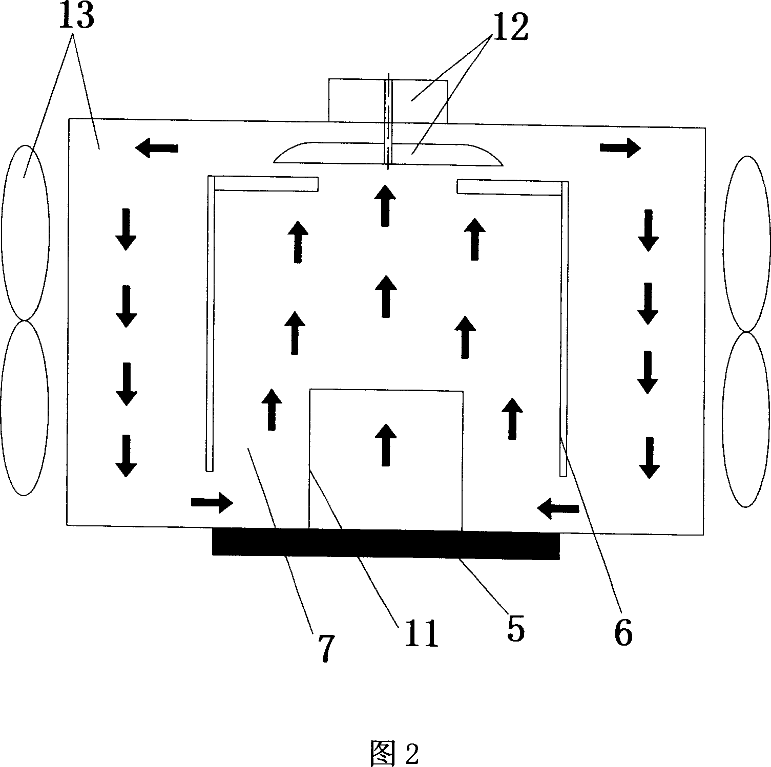
[0019] Referring to FIG. 2 , Embodiment 2 is the same as Embodiment 1, except that the liquid driver is a miniature centrifugal pump 12 . The blades of the micro-centrifugal pump 12 are arranged in the cavity. When the micro-centrifugal pump rotates, the cooling liquid 7 that has absorbed the heat of the heat source flows, and then drives these hot fluids to flow into a plurality of cooling channels provided on the inner wall of the radiator, and the cooling liquid The heat carried by 7 is transmitted to the environment through the outer wall of the heat sink and the fan, and the temperature of the cooling liquid 7 drops. When the cooled cooling liquid 7 returns to the bottom of the radiator housing 6, it will absorb the heat of the heat source again and start a new process. cycle. In order to obtain a large fluid driving force and lower noise, the micro motor should use a high-speed DC motor.

Embodiment 3

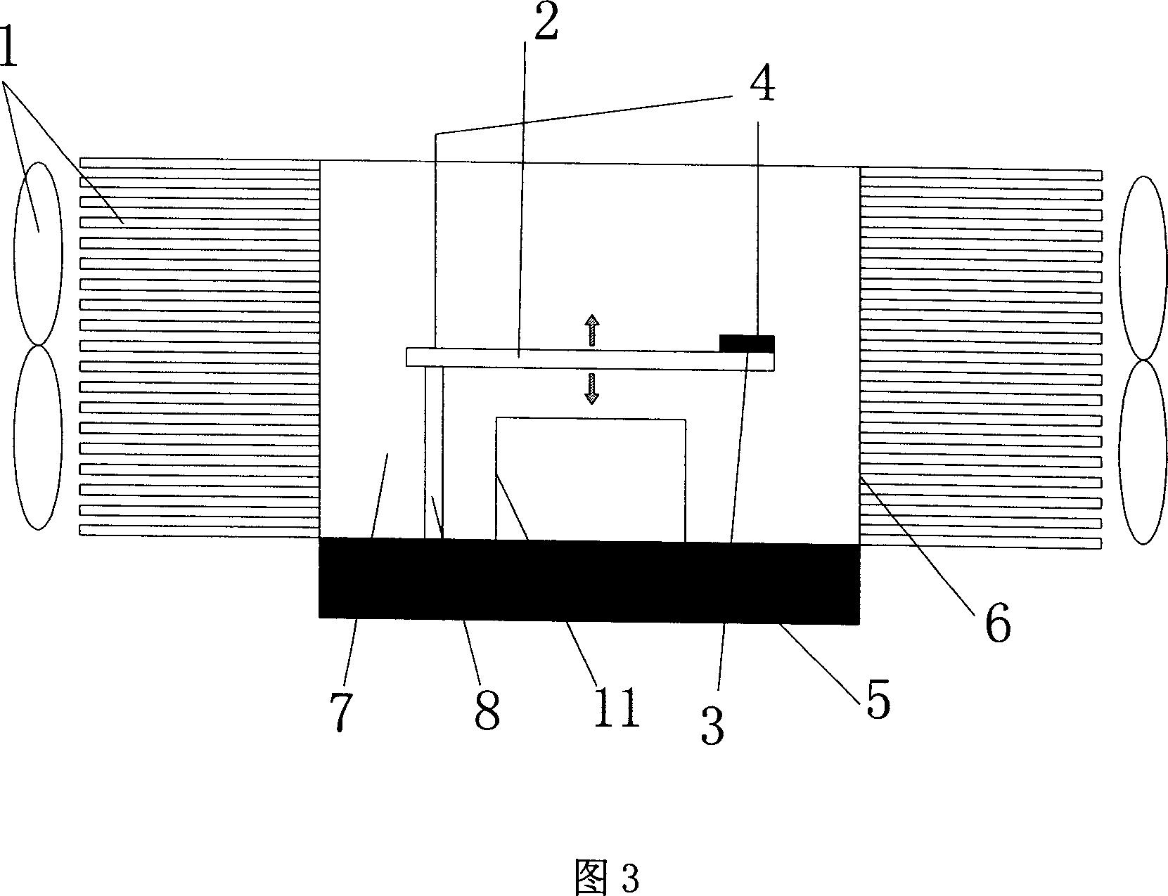
[0021] Referring to Fig. 3, embodiment 3 is the same as embodiment 2, the difference is that the liquid driver is a piezoelectric driver, the piezoelectric driver is composed of a cantilever beam 2 and a support frame 8, and the cantilever beam 2 is a flexible beam, and its working principle is as follows : When the piezoelectric driver 3 is connected to the power supply through the wire 4, the piezoelectric driver 3 starts to vibrate. Due to the characteristics of the cantilever beam, the driving force will cause a large deformation of the cantilever beam, and the deformation of the cantilever beam will drive the radiator shell 6 The cooling liquid 7 inside produces movement, and the cooling liquid 7 in contact with the heat source quickly flows to other positions of the container after absorbing heat, and the heat carried by these hot fluids is transferred to the surrounding environment through the radiator fins 14 and the fan 1 on the four walls In order to lower the tempera...


PUM


Abstract

A heat dissipater employing inner liquid circulation mainly includes a heat sink, a heat dissipater, cooling liquid, a fan and a liquid driver; and is characterized in that a chamber is arranged in the heat dissipater; the heat sink and the liquid driver are arranged in the chamber; the cooling liquid forms enclosed inner circulation system in the heat dissipater chamber under action of the liquid driver; the heat dissipater is made of highly heat-conductive material; the heat sink and the fan are arranged on four walls or two walls of the heat dissipater, and a plurality of heat dissipating passages are arranged on inner wall of the heat dissipater. The invention has the advantages of adopting enclosed inner circulation cooling system, no requirement for pipeline connection, no leakage, convenient process, good cooling efficiency as well as high reliability.

Description

technical field [0001] The invention relates to a radiator for electronic devices, in particular to a radiator for electronic devices using liquid internal circulation. technical background [0002] The essence of the working process of any electronic device is the energy conversion process, which is always accompanied by heat generation. The root cause of heat generation is that any energy conversion process cannot be 100% efficient, and all or most of the energy that is less than 100% becomes heat. Existing electronic devices are developing in the direction of smaller, higher speed, and higher power density, which means greater heat flux density. Supercomputers are mainly composed of high-power density electronic components such as microprocessors and control circuits. The density is very high, on the order of 100W / cm 2 around or higher. Due to volume limitations, high-performance servers and notebooks also have a very high heat flux density. In order to maintain normal...

Claims


Application Information

Patent Timeline
IPC IPC(8): H05K7/20G12B15/02G06F1/20H01L23/473
CPCH01L2924/0002
Inventor 刘胜罗小兵陈伟
Owner 刘胜
Why Eureka
Try Eureka