Double-system sanitary sewage purifying biogas generating pit

A domestic sewage and dual-system technology, applied in biological sludge treatment, anaerobic digestion treatment, waste fuel, etc., can solve the problems of short service life, long construction period, affecting use, etc., and achieve long service life, convenient construction, The effect of compact equipment

Inactive Publication Date: 2008-04-02
管印贵
View PDF0 Cites 9 Cited by
  • Summary
  • Abstract
  • Description
  • Claims
  • Application Information

AI Technical Summary

Problems solved by technology

[0003] In order to overcome the various shortcomings and deficiencies of the existing domestic sewage purification biogas digesters, the present invention provides a dual-system domestic sewage purif

Method used


Image

  • Double-system sanitary sewage purifying biogas generating pit

Examples


Embodiment Construction

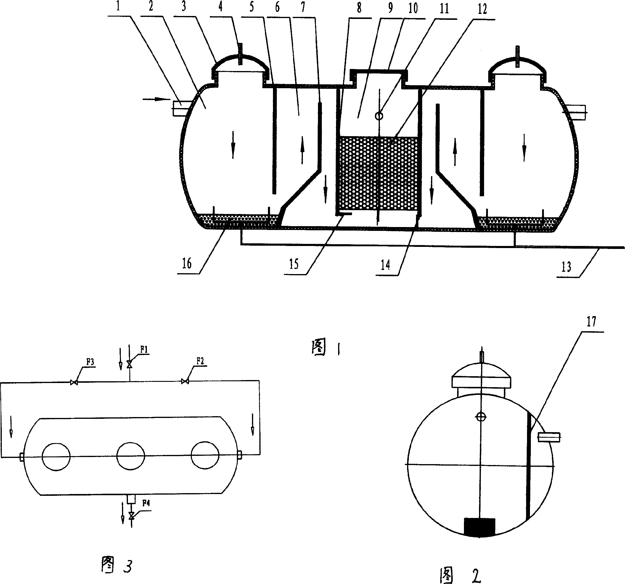
[0014] The present invention is made of glass fiber reinforced plastics, has an integral structure, and has a multi-stage self-flow and overflow anaerobic consumption system.

[0015] 1. As shown in the figure, the structure of the biogas digester consists of five parts: two primary anaerobic chambers (2), two secondary anaerobic chambers (6), two water inlets (1), and two water outlets (11) and a biological filtration chamber (9), wherein the primary anaerobic chamber (2), the secondary anaerobic chamber (6), and the biological filtration chamber (9) constitute a processing system.

[0016] 2. The primary anaerobic chamber (2) and the secondary anaerobic chamber (6) are separated by a primary partition (5), and the lower part of the primary partition (5) has a through hole, which is used as the digested biogas slurry to flow to the secondary Access to the anaerobic chamber (6). There is an anaerobic bacteria sludge layer (16) at the bottom of the primary anaerobic chamber (2...


PUM


Abstract

The present invention provides a double-system sewage purifying biomass pool, which relates to a sewage purifying biomass pool. The present invention essentially comprises a water inputting mouth, a first-class anaerobic room, a second-class anaerobic room and a biological filter room. The present invention integrated two systems to a whole, which is provided with two first-class anaerobic rooms, two second-class anaerobic rooms and one biological filter room; the biological filter room is connected with the two systems. The first-class anaerobic room is separated from the second-class anaerobic room by a partition. An anaerobic sludge layer is arranged at the bottom of the first-class anaerobic room. A second-class partition is arranged in the second-class anaerobic room, which divides the second-class anaerobic room into a front part and a back part. The present invention adopts an integrated design. The risk of leaking is reduced; the equipment is compact; the occupied acreage is small; the production efficiency is high; industrialized production is easily to be realized; the scene operating time is reduced and the installing and constructing are convenient. The present invention has the advantages of high strength, corrosion resistant, low thermal conductivity, and good heat preserving effect and long service time and so on.

Description


Claims


Application Information

Patent Timeline
Owner 管印贵
Why Eureka
Try Eureka