Optical fiber distributed temperature and stress sensing device

An optical fiber distributed, stress sensing technology, applied in the field of sensing

Inactive Publication Date: 2008-04-09
BEIHANG UNIV
View PDF0 Cites 47 Cited by
  • Summary
  • Abstract
  • Description
  • Claims
  • Application Information

AI Technical Summary

Problems solved by technology

Compared with the existing coherent detection means, the optical fiber distributed temperature and stress sensing device of the present invention effectively solves the problem of cross-sensitivity between multiple ...

Method used


Image

  • Optical fiber distributed temperature and stress sensing device
  • Optical fiber distributed temperature and stress sensing device
  • Optical fiber distributed temperature and stress sensing device

Examples


Embodiment Construction

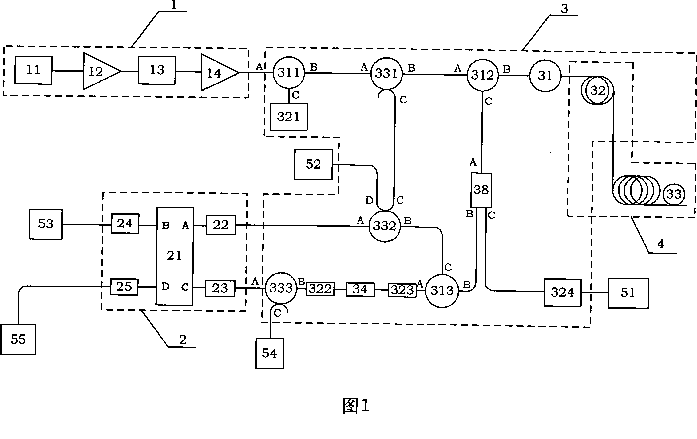
[0012] The present invention will be further described in detail below in conjunction with the accompanying drawings and embodiments.

[0013] Please refer to Fig. 1, the present invention is an optical fiber distributed temperature and stress sensing device, based on optical fiber Raman scattering as temperature information carrier, Brillouin scattering as stress information carrier, using Rayleigh scattering to measure the relative Discriminator frequency and frequency offset, using Fabry-Perot etalon for frequency discrimination, and a direct detection method for simultaneous distributed sensing of temperature and stress. It mainly includes three modules: a light source 1, a frequency discriminator 2, and a constant temperature box 3. The connection relationship of the devices in each module is: the fiber laser 11 output pigtail and the first erbium-doped fiber amplifier 12 The input fiber fusion splicing, the first The fiber pigtail of the erbium-doped fiber amplifier 12 i...


PUM

PropertyMeasurementUnit
Center wavelengthaaaaaaaaaa

Abstract

The invention discloses a sensing device of optical fiber distribution type temperature and stress and mainly comprises a light source module (1), a frequency discriminator module (2), and a thermo tank module (3), which are all connected with one another by polarization-preserving fiber. The invention is a direct detection method which is based on optical fiber Raman scattering used as a carrier wave of temperature information, brillouin scattering used as a carrier wave of stress, rayleigh scattering used for measuring relative frequency of a outgoing laser beam to a frequency discriminator and Fabry-Perot etalon used for discriminating frequency and distributing sensing temperature and stress. The invention has the advantages of simple structure, fine stability, avoidance of outgoing power of the light source during coherent detection, outgoing frequency of the light source. Instability of acoustic modulation or electro-optic modulation frequency is directly referred to measure errors and the direct detection technology of the frequency discrimination is not sensitive to frequency drift of the light source and fluctuation of signal intensity.

Description

technical field [0001] The invention relates to a sensing technology, more particularly, to a temperature and stress sensing device connected by an all-optical fiber. Background technique [0002] Distributed optical fiber sensors can be embedded in the material structure to form a smart material structure (Smart Structure) to realize real-time self-detection and self-diagnosis of the structure itself, which can be applied to: (1) high-rise buildings, intelligent buildings, bridges, highways and other disastrous Online, dynamic detection, protection and alarm; (2) Online, dynamic detection of aviation and aerospace vehicles and neural network system of robots; (3) Temperature distribution measurement, thermal protection and fault diagnosis of various large and medium-sized transformers and generator sets , underground and overhead high-voltage power cables, thermal power plant piping temperature detection, heating system (warm water, heating) pipes; (4) in the coal mine and ...

Claims


Application Information

Patent Timeline
IPC IPC(8): G01D5/353G01K11/32G01L1/24G01L11/02G02B6/255G02B6/34G02B6/42G02B6/36G02B6/26G01K11/322G01K11/324
Inventor 杨远洪夏海云牟宏谦
Owner BEIHANG UNIV
Why Eureka
Try Eureka