Millimeter wave MEMS phase shifter of sawtooth shape coplane wave-guide structure

A coplanar waveguide and sawtooth technology is applied in the field of miniaturized millimeter wave phase shifters, which can solve the problems of low phase accuracy and small phase shift of a single bridge, and achieve the effects of increasing reflection loss, small size and increasing cost.

Inactive Publication Date: 2008-04-09
HARBIN INST OF TECH
View PDF0 Cites 11 Cited by
  • Summary
  • Abstract
  • Description
  • Claims
  • Application Information

AI Technical Summary

Problems solved by technology

[0005] In order to solve the problems of small single-bridge phase shift and low phase accuracy in existing MEMS phase shifters, the present invention provides a millimeter-wave MEMS phase shifter with a zigzag coplanar waveguide structure

Method used


Image

  • Millimeter wave MEMS phase shifter of sawtooth shape coplane wave-guide structure
  • Millimeter wave MEMS phase shifter of sawtooth shape coplane wave-guide structure
  • Millimeter wave MEMS phase shifter of sawtooth shape coplane wave-guide structure

Examples


specific Embodiment approach 1

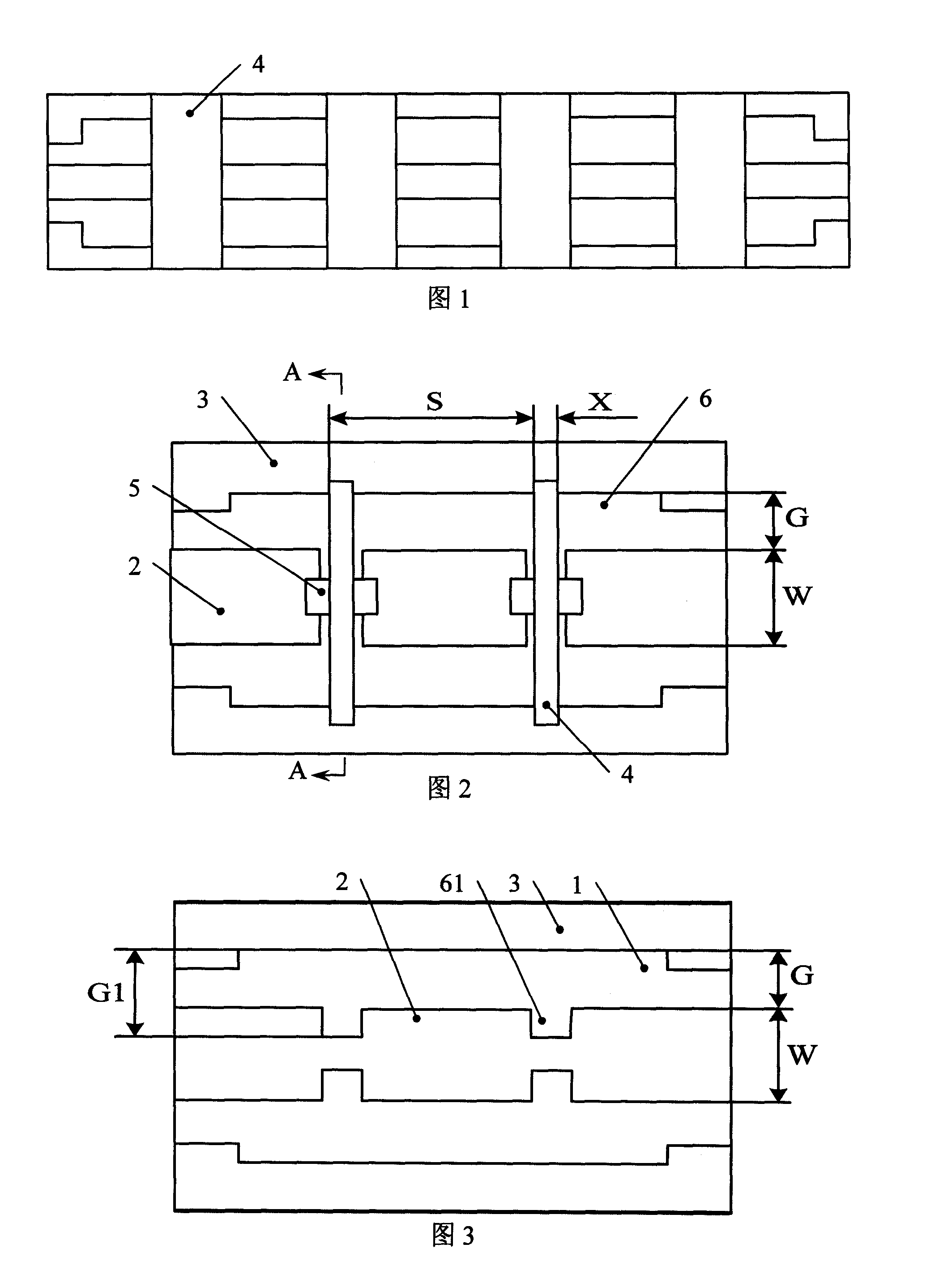
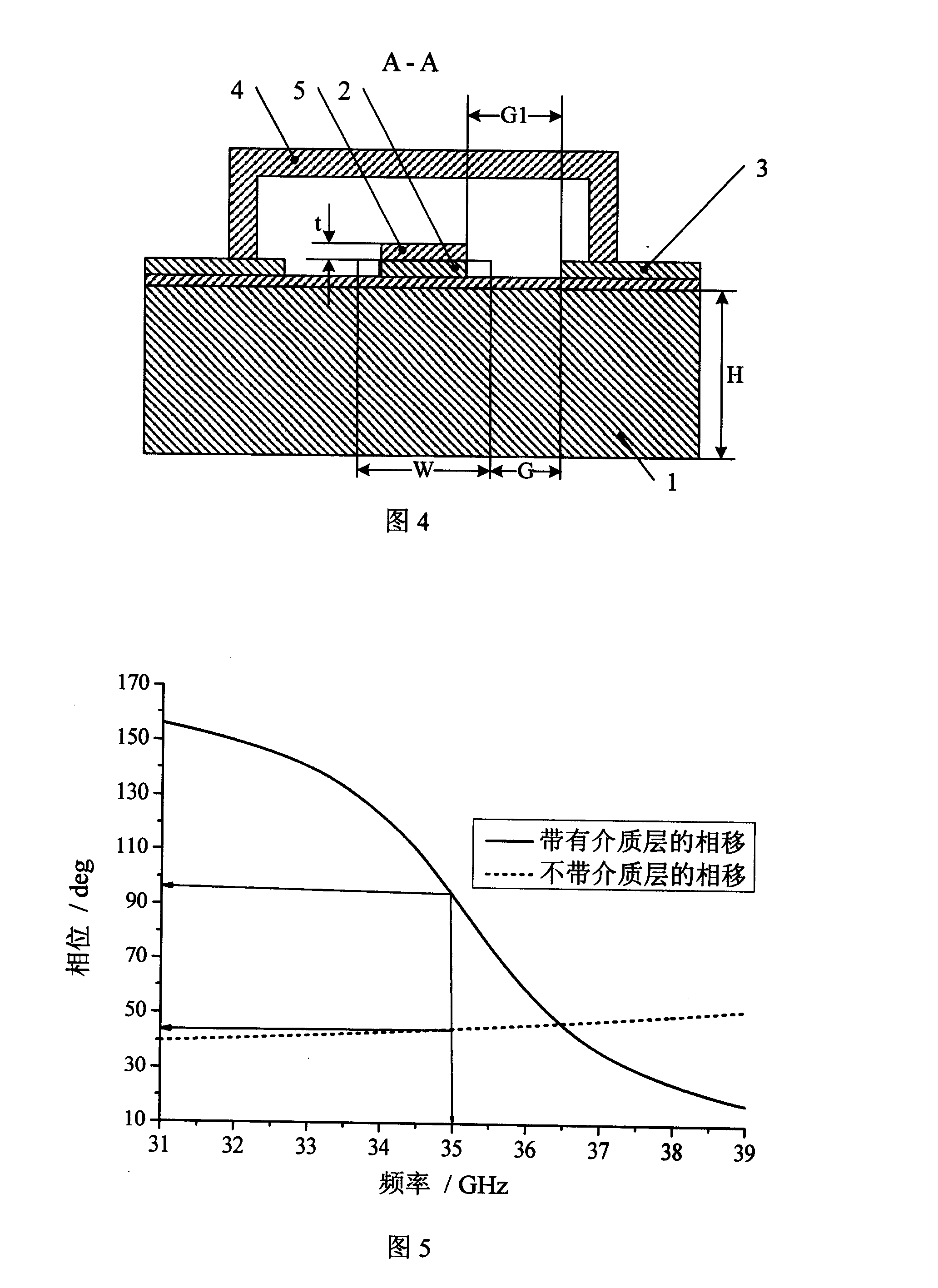
[0008] Specific Embodiment 1: Refer to FIG. 2 to FIG. 4 to illustrate this embodiment. The millimeter-wave MEMS phase shifter with a zigzag coplanar waveguide structure described in this embodiment includes a coplanar waveguide 6 and n metal bridges 4, and the coplanar waveguide 6 is composed of a substrate 1, a signal line 2, and two ground lines 3 The signal line 2 is fixed in the middle of the upper surface of the substrate 1, and the ground wire 3 is fixed at intervals on both sides of the signal line 2. The metal bridge periodically straddles the substrate 1 of the coplanar waveguide 6. The metal bridge 4 and The signal lines 2 are vertical, and the two ends of each metal bridge 4 are respectively fixed on the two ground wires 3 on the coplanar waveguide 6. It also includes n insulating dielectric substrates 5, and each metal bridge 4 is positive Both sides of the lower signal line 2 have symmetrical inwardly recessed sawtooth 61, and a dielectric substrate 5 is fixed on ...

specific Embodiment approach 2

[0010] Embodiment 2: This embodiment differs from the millimeter-wave MEMS phase shifter with a zigzag coplanar waveguide structure described in Embodiment 1 in that the dielectric constant of the dielectric substrate 5 is 2-11.

specific Embodiment approach 3

[0011] Embodiment 3: The difference between this embodiment and the millimeter-wave MEMS phase shifter with a zigzag coplanar waveguide structure described in Embodiment 1 is that the dielectric constant of the dielectric substrate 5 is 11-20.


PUM

PropertyMeasurementUnit
Thicknessaaaaaaaaaa
Thicknessaaaaaaaaaa
Thicknessaaaaaaaaaa

Abstract

A zigzag coplanar waveguide-structured millimeter-wave MEMS phaser relates to a minimized millimeter-wave phaser, which resolves the problem that the prior MEMS phasers have small single-bridge phase shift and low phase precision. The invention comprises a coplanar waveguide and n metal bridges, the coplanar waveguide is composed of a base plate, a signal wire and two ground wires, the signal wire is fixed on the middle of the upper surface of the base plate, the ground wires are fixed on the two sides of the signal wire at intervals, the metal bridges periodically cross the base body of the coplanar waveguide, and the two ends of each metal bridge are respectively fixed on the ground wires on the coplanar waveguide; the invention also comprises n dielectric substrates, the two sides of the signal wire right under each metal bridge have symmetric zigzag concaving inwards, the dielectric substrates are fixed on the surface of the signal wire corresponding to the zigzag, and the dielectric constant of the dielectric substrates is 2-20 and the thickness t is 0.1Mu m-5Mum. The invention can be widely applied to a radio frequency communication system and a small-sized phased array radar, a phased array antenna system and so on.

Description

technical field [0001] The invention relates to a miniaturized millimeter wave phase shifter. Background technique [0002] The phase shifter is the most important part of the core components in phased array radar, satellite communication, and mobile communication equipment. Its operating frequency band and insertion loss directly affect the anti-interference ability and sensitivity of these equipment, as well as the weight and volume of the system. and cost. In traditional phase shifter circuits, diodes or ferrite devices are often used as the main components of phase shifter circuits, but traditional phase shifters have disadvantages such as high power consumption, high insertion loss, poor reliability, and high cost. Moreover, it is not feasible to use traditional phase shifters to design the feed network of millimeter-wave (such as Ka-band) phased arrays, because the spacing between array elements is on the order of millimeters, which is even smaller than the physical s...

Claims


Application Information

Patent Timeline
IPC IPC(8): H01P1/18
Inventor 吴群傅佳辉杨国辉贺训军孟繁义唐恺
Owner HARBIN INST OF TECH
Why Eureka
Try Eureka