
Narrow pulse pull-down current type level displacement circuit

A technology of level shifting circuit and pulling current, applied in the field of electronics, can solve the problems of being unsuitable for high-voltage applications, increasing circuit complexity, and high device requirements, and achieving the effect of widening the scope of application, low power consumption, and simplifying the circuit structure

Inactive Publication Date: 2008-04-09
UNIV OF ELECTRONIC SCI & TECH OF CHINA
View PDF0 Cites 21 Cited by
  • Summary
  • Abstract
  • Description
  • Claims
  • Application Information

AI Technical Summary

Problems solved by technology

However, since the rising edge and falling edge of the control signal are converted into narrow pulses respectively, the circuit is very complicated
In addition, the logic level on the high side is obtained directly from the voltage across the load resistor R1 or R2, and the displacement current when the power switch is turned on or off can easily generate voltage fluctuations on the load resistors R1 and R2, resulting in false trigger signals
Therefore, a certain pulse filter circuit must be used at the high voltage end to eliminate false trigger signals, which also increases the complexity of the circuit
[0007] To sum up, the currently used level shifting circuit has complex circuits, high device requirements, and is not suitable for high-voltage applications.

Method used


Image

  • Narrow pulse pull-down current type level displacement circuit
  • Narrow pulse pull-down current type level displacement circuit
  • Narrow pulse pull-down current type level displacement circuit

Examples


Embodiment approach 1

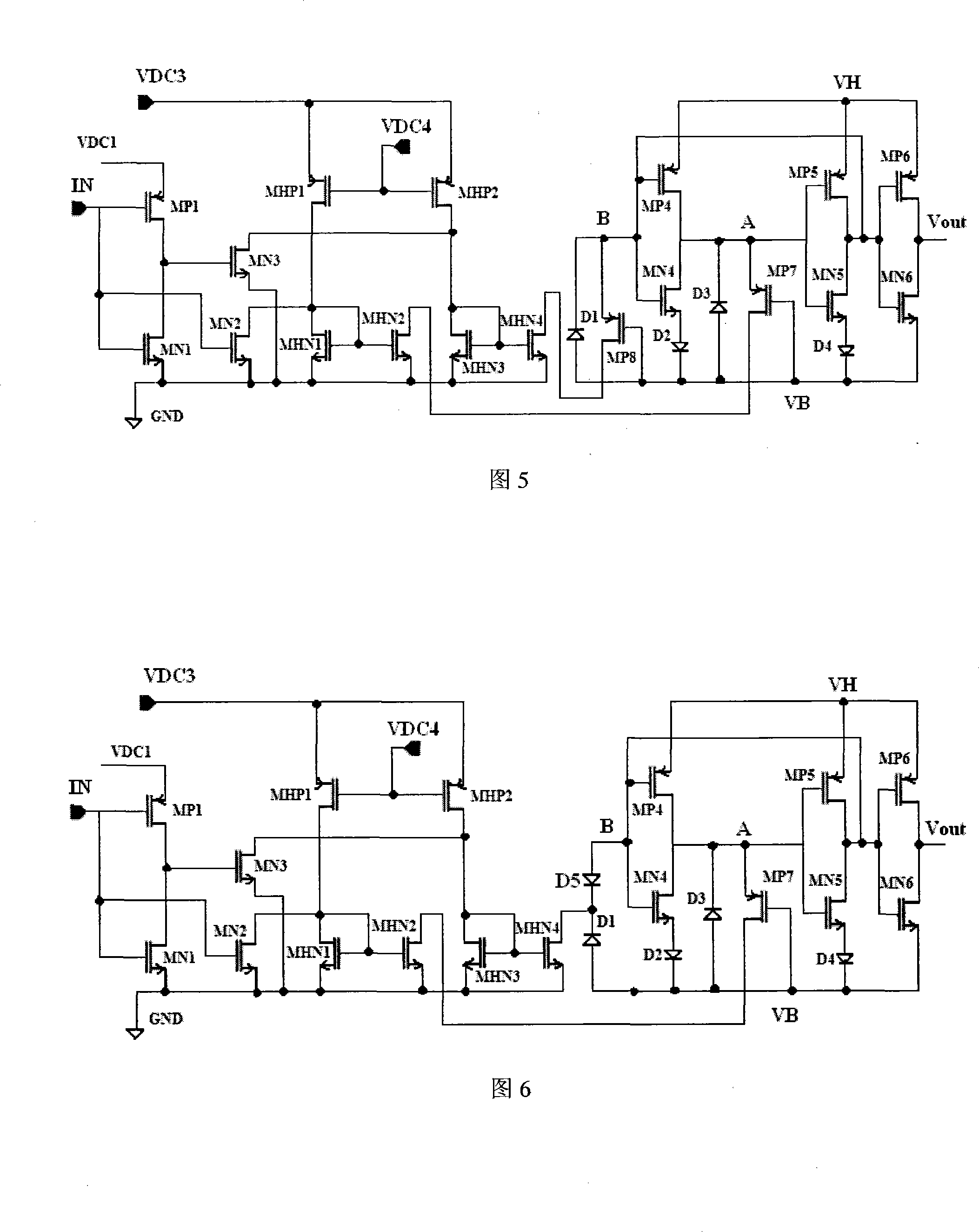
[0025] As shown in Figure 5: the input buffer 1 circuit unit is composed of PMOS transistor MP1 and NMOS transistor MN1, the constant current source switch A circuit unit is composed of PMOS transistor MHP1 and NMOS transistors MN2, MHN1 and MHN2, and the constant current source switch B circuit unit is composed of PMOS transistor MHP2 is composed of NMOS transistors MN3, MHN3 and MHN4. Pulse self-generating A circuit unit is composed of PMOS transistor MP7 and diode D3. Pulse self-generating B circuit unit is composed of PMOS transistor MP8 and diode D1. Gate pull-down 6 circuit unit is composed of PMOS transistors MP4, MP5, NMOS transistors MN4, MN5 and diodes D2, D4 are composed, and the circuit unit of the inverter 7 is composed of PMOS transistors MP6 and NMOS transistors MN6. The DC power supply VDC2 is composed of a DC power supply VDC3 and a DC power supply VDC3, wherein the voltage of the DC power supply VDC3 is higher than that of the DC power supply VDC3.

[0026] T...

Embodiment approach 2

[0062] As shown in Figure 6: the input buffer 1 circuit unit is composed of PMOS transistor MP1 and NMOS transistor MN1, the constant current source switch A circuit unit is composed of PMOS transistor MHP1 and NMOS transistors MN2, MHN1 and MHN2, and the constant current source switch B circuit unit is composed of PMOS transistor MHP2 is composed of NMOS transistors MN3, MHN3 and MHN4. Pulse self-generating A circuit unit is composed of PMOS transistor MP7 and diode D3. Pulse self-generating B circuit unit is composed of diodes D1 and D5. Gate pull-down 6 circuit unit is composed of PMOS transistor MP4, MP5 are composed of NMOS transistors MN4, MN5 and diodes D2, D4, and the circuit unit of the inverter 7 is composed of PMOS transistor MP6 and NMOS transistor MN6. DC power supply VDC2 is composed of DC power supply VDC3 and DC power supply VDC3, wherein the voltage of DC power supply VDC3 is higher than that of DC power supply VDC3, and the timing of high-end floating power su...

Embodiment approach 3

[0069] As shown in Figure 7, the input buffer 1 circuit unit is composed of PMOS transistor MP1 and NMOS transistor MN1, the constant current source switch A circuit unit is composed of PMOS transistor MHP1 and NMOS transistors MN2, MHN1 and MHN2, and the constant current source switch B circuit unit is composed of PMOS transistor MHP2 is composed of NMOS transistors MN3, MHN3 and MHN4. Pulse self-generating circuit unit A is composed of diodes D3 and D6. Pulse self-generating circuit unit B is composed of PMOS transistor MP8 and diode D1. Gate pull-down 6 circuit unit is composed of PMOS transistor MP4, MP5 are composed of NMOS transistors MN4, MN5 and diodes D2, D4, and the circuit unit of the inverter 7 is composed of PMOS transistor MP6 and NMOS transistor MN6. DC power supply VDC2 is composed of DC power supply VDC3 and DC power supply VDC3, wherein the voltage of DC power supply VDC3 is higher than that of DC power supply VDC3; the timing of high-end floating power supply...


PUM


Abstract

The invention belongs to the field of electronic technology and relates to an integrated level displacement circuit, which consists essentially of seven circuit units including input buffer 1, permanent current source switch A and B, pulse self-generating A and B, grid electrode pull-down 6 and phase inverter 7. Through inputting buffer 1, low logic signal IN generates in-phase and anti-phase control signals S1 and S2 used for controlling permanent current source switch A and B to obtain permanent current output signal S3 and S4; obtains narrow pulse pull-down current S5 and S6 through pulse self-generating A and pulse self-generating B circuit; and generates VB-VH floating level displacement signal S7 through grid electrode pull-down 6 circuit. After S7 passes through phase inverter 7, high logic signal Vout-VB that is the same as and synchronous with the low logic signal IN will be generated between the output end of the phase inverter 7 and the high-end floating VB. The invention has advantages of simplicity of circuit, low requirements for the device, low self-consumption of power, mis-triggering avoidance, stable working condition, easiness for integration and suitability for high-pressure application.

Description

technical field [0001] The invention belongs to the field of electronic technology, relates to an integrated level shift circuit, and simultaneously relates to a driving circuit of a floating high-end MOS switch. Background technique [0002] In the intelligent power integrated circuit of the bridge power switch structure, the high-side bridge arm and the low-side bridge arm are composed of power MOS or IGBT. The driving of the high-side bridge arm has the following basic requirements: First, the lower logic level compatible with CMOS / TTL logic needs to be shifted to the high logic level that can drive the power switch. Second, in order to make the working states of the high-side and low-side MOS switches symmetrical, the same logic level as that of the low-side MOS switch must be provided between the gate and source of the high-side MOS switch. However, in the switching process of the high-side bridge arm, the source potential of the power MOS used as a high-side switch fl...

Claims


Application Information

Patent Timeline
IPC IPC(8): H03K19/0175H03K19/0185H03K17/687
Inventor 方健乔明张波周贤达刘伦友刘哲毛焜张弦
Owner UNIV OF ELECTRONIC SCI & TECH OF CHINA
Features
  • Generate Ideas
  • Intellectual Property
  • Life Sciences
  • Materials
  • Tech Scout
  • Unparalleled Data Quality
  • Higher Quality Content
  • 60% Fewer Hallucinations
Learn More