
Signal output method of light receiver area array sensor

A photoelectric sensor and sensor technology, applied in the direction of image communication, color TV parts, TV system parts, etc., can solve the problems of output pixel selection, synchronization problem, difficult to meet the sampling rate and other problems

Inactive Publication Date: 2008-04-09
EAST CHINA UNIV OF SCI & TECH
View PDF0 Cites 27 Cited by
  • Summary
  • Abstract
  • Description
  • Claims
  • Application Information

AI Technical Summary

Problems solved by technology

[0009] However, if a similar image sensor is used as the detection device of a multi-channel optical receiver, in addition to the detection sensitivity, response time, response frequency band and other parameters involved in conventional photoelectric detection, there will be two problems: one is the selection of output pixels problem; one is the synchronization of output sampling and received light
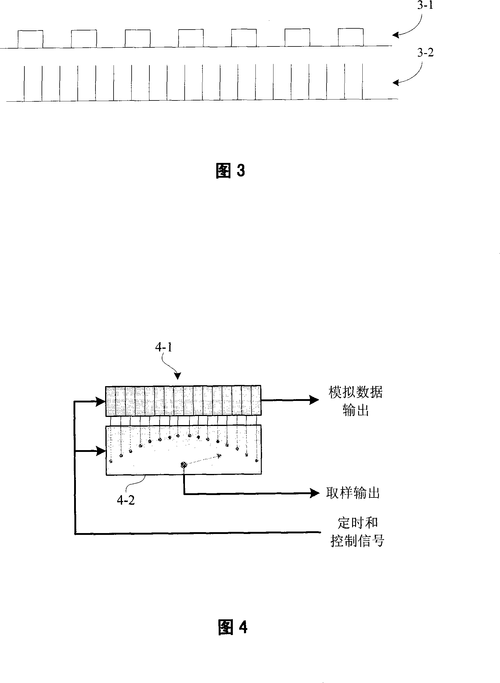
But if the detector adopts sampling output, theoretically speaking, only by increasing the sampling frequency of the output to more than twice the bandwidth of the optical pulse signal according to the Nyquist sampling theorem can it be possible to maintain the integrity of the information
If the expected communication data rate is high, the corresponding optical pulse frequency is high, and this sampling rate is difficult to meet

Method used


Image

  • Signal output method of light receiver area array sensor
  • Signal output method of light receiver area array sensor
  • Signal output method of light receiver area array sensor

Examples


Embodiment Construction

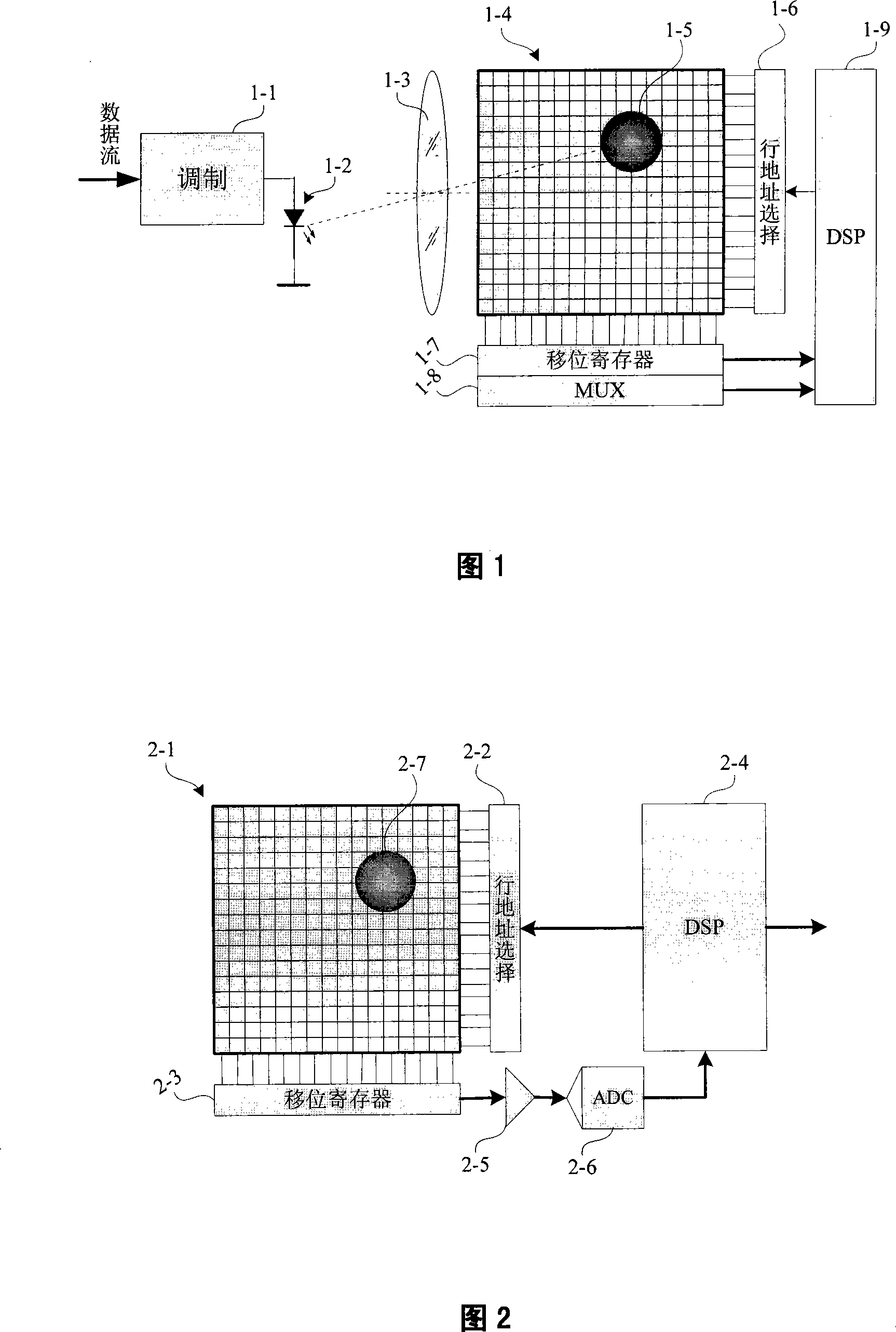
[0033] The optical receiver based on the area array photoelectric sensor can theoretically perform space division multiplex communication through the imaging system. However, to simplify the description of the present invention, a single sending light source is taken as an example. Figure 1 is a simplified optical communication system. At the optical sending end, the sent data stream is modulated by a modulator (1-1) into a pulse signal and sent out through a light-emitting diode (1-2). At the light receiving end, through the imaging optical system (1-3), the light source at the sending end is imaged on the image sensor (1-4) to form a light spot (1-5). The image sensor (1-4) is composed of many pixels, and each small square in the figure represents a pixel, but the 16×16 small squares shown in Figure 1-4 do not represent the actual size of the image sensor. Often it can be much larger. Usually, this kind of optical wireless communication system is mostly used for indoor sh...


PUM


Abstract

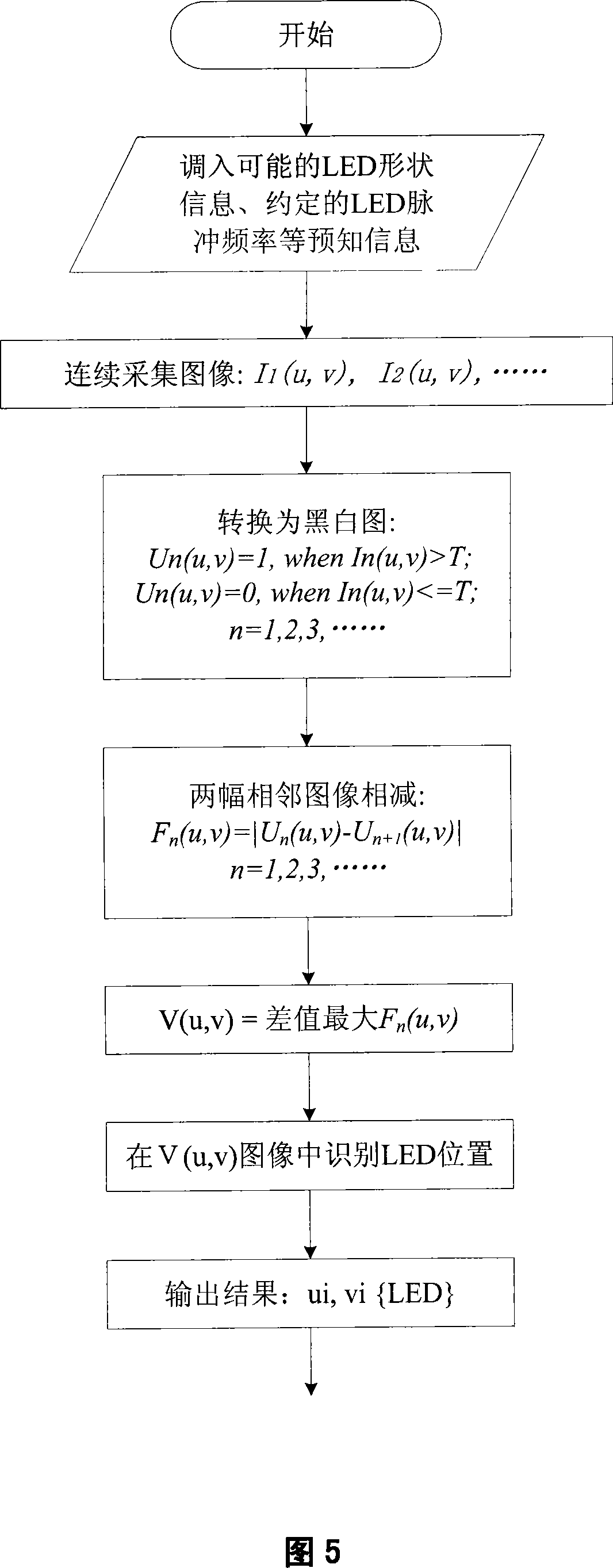
The invention provides a signal output method of an optical receiver area array sensor, wherein the receiver firstly identifies and responds pixel positions of useful optical signals according to space and time characters of a light source, then selectively outputs the pixel signals and removes the pixel output only responding environment light. Meanwhile, the invention introduces a synchronous sampling technology for synchronizing the output sampling of the area array sensor and the frequency of light pulse and ensuring the integrity of signals during high speed communication.

Description

technical field [0001] The invention belongs to the field of optical wireless communication, in particular to a signal output method of an optical receiver with an imaging optical system and an area array photoelectric sensor. Background technique [0002] Optical communication systems can be divided into wired communication and wireless communication from the channel point of view. The current main technology of optical cable communication is optical fiber communication, which has become the backbone technology in the transmission network. In terms of the characteristics of the emitted light used in the optical wireless communication system, there are currently two main types: laser communication and infrared communication. Laser communication is generally used in relatively long-distance point-to-point communication. One of the main technologies of infrared communication is the IrDA (International Infrared Data Association) standard for short-range data exchange of portab...

Claims


Application Information

Patent Timeline
Patent Type & Authority Applications(China)
IPC IPC(8): H04N5/33
Inventor 樊凌涛
Owner EAST CHINA UNIV OF SCI & TECH
Learn More