Magnetron sputtering cathode target for ultrahigh vacuum system

A magnetron sputtering and ultra-high vacuum technology, which is applied in sputtering coating, vacuum evaporation coating, ion implantation coating, etc., can solve the problem of restricting the electrical performance and yield of semiconductor devices and integrated circuits, and affecting the passivation film. Purity and density, sputtering equipment instability and other issues, to achieve the effect of isolating direct contact, easy maintenance and replacement, and guaranteed quality

Inactive Publication Date: 2008-04-16
HEFEI INSTITUTES OF PHYSICAL SCIENCE - CHINESE ACAD OF SCI
View PDF1 Cites 8 Cited by
  • Summary
  • Abstract
  • Description
  • Claims
  • Application Information

AI Technical Summary

Problems solved by technology

However, there are deficiencies in this sputtering target. First of all, after the magnet seal cover is filled with pure iron, magnets and cooling system, if it is welded and packaged, it will be difficult to carry out necessary maintenance and maintenance of each component in it in the future. Replacement, if it is a cover-type package, air leakage and water seepage will easily occur at the package; secondly, as the cathode, it needs to be electrically insulated from other parts in the sputtering equipment, and the insulating layer is made of non-metallic materials. Just can't use the mode of welding to solve mutual sealing problem; Again, because of the defect on the structure, the vacuum degree of sputtering equipment can only reach 10 -6 Pa, this will not avoid the residual gases in the system, such as oxygen, nitrogen, and water vapor, to react with the target to form oxide nitride, thereby increasing the contact resistance of the sputtered metal film or affecting the purity and purity of the passivation film. Density, which in turn restricts the electrical performance and yield of semiconductor devices and integrated circuits; finally, the magnets that are always placed in cooling water are extremely prone to corrosion. In the long run, it is inevitable that their functions will not be affected, which will eventually lead to the overall corrosion of the sputtering equipment. Instability of work and increase in use and maintenance costs

Method used


Image

  • Magnetron sputtering cathode target for ultrahigh vacuum system

Examples


Embodiment Construction

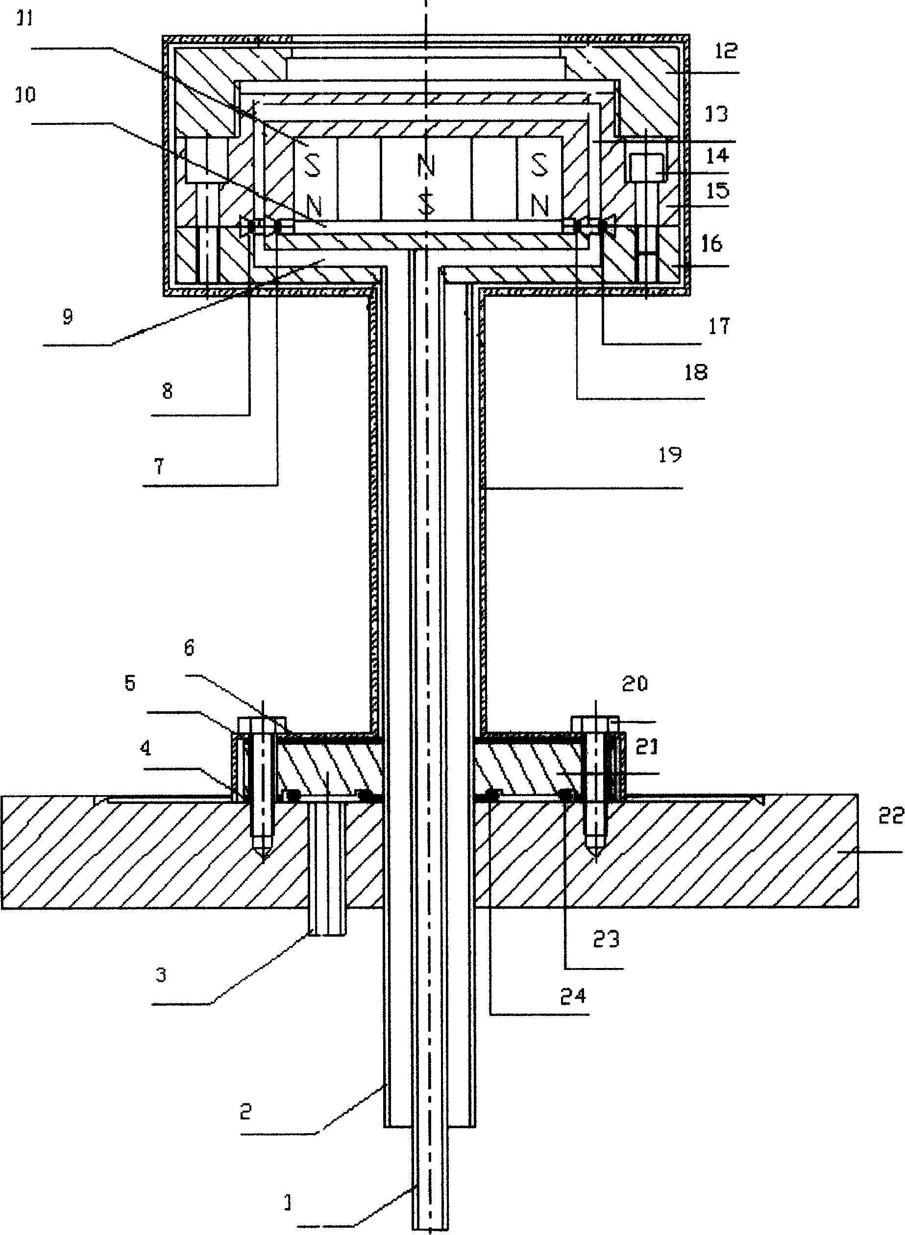
[0010] see figure 1 , the water-cooling component is composed of the covered winding cooling water tank 13 built in the connected upper flange 15, the cooling water tank 9 built in the lower flange 16, the water inlet pipe 1 and the water outlet pipe 2; wherein, the water inlet pipe 1 is set in the outlet pipe 2, and the cooling water tank 9 is cut off and welded and communicated with it, and the outlet pipe 2 is welded and communicated with the remainder of the cooling water tank 9. The cavity of the upper flange 15 is provided with a magnet holder 10 made of soft iron and a magnet 11 located on it, the upper end and the target mounting cover 12 are screwed together through their mutual threads, the lower end surface and the lower flange 16 is interposed with two metal sealing rings (17,18), and is fixedly connected through screw 14 phases. Two metal sealing rings (17, 18) are oxygen-free copper sealing rings, which are respectively located at the inner layer knife edge 7 an...


PUM


Abstract

The invention discloses a magnetic control sputtering cathode target for an ultrahigh vacuum system. An upper flange and a lower flange (15 and 16) are inside provided with cooling troughs (13 and 9) which are communicated with each other, a water inlet pipe and a water outlet pipe (1 and 2) which separate from the cooling trough (9) are welded with the cooling trough (9), the upper end part of the upper flange (15) is in screw joint with a target material mounting frame (12), the chamber of the upper flange is inside provided with a magnet holder (10) and a magnet (11), metal obturating rings (17 and 18) which are positioned at an inner layer and an outer layer edges (7 and 8) are arranged between the lower end surface of the upper flange and the lower flange (16) and are fixed by a bolt (14), a small flange (21) is welded outside the water outlet pipe (2); insulation sheets (4 and 6) are arranged between the small flange (21) and a shield enclosure (19) and a base flange (22), two O-shaped cushion rubbers are arranged between the small flange and the base flange (22) which is communicated with an exhaust tube (3), the two cushion rubbers are fixed by a bolt (20) sleeved by an insulating sleeve (5). The invention has a vacuum degree up to 6x10<-8>Pa, which can realize the preparation of metal or nonmetal film with high quality and purity.

Description

technical field [0001] The invention relates to a magnetron sputtering cathode target, in particular to a magnetron sputtering cathode target used in an ultra-high vacuum system. Background technique [0002] With the rapid development of semiconductor devices, especially semiconductor integrated circuit technology, the preparation of semiconductor surface contact metal electrodes and the passivation process of semiconductor surface are particularly important. The preparation of the above metal and non-metal thin films by magnetron sputtering is one of the most commonly used technical methods. It is characterized by stable process, easy control of film thickness, deposition of high-energy particles, and good compactness of film formation. Technology has become the most commonly used technology for the production of semiconductor devices, especially the preparation of integrated circuits. For example, "a planar magnetron sputtering target" disclosed in Chinese Utility Model ...

Claims


Application Information

Patent Timeline
Patent Type & Authority Applications(China)
IPC IPC(8): C23C14/35
Inventor 李新化邱凯尹志军钟飞陈家荣
Owner HEFEI INSTITUTES OF PHYSICAL SCIENCE - CHINESE ACAD OF SCI
Why Eureka
Try Eureka