Acceleration sensor

An acceleration sensor and acceleration technology, applied in the direction of acceleration measurement using inertial force, etc., can solve the problems of difficulty in ensuring long-term reliability of the joint, difficulty in improving position accuracy, and difficulty in miniaturization, etc., to ensure long-term reliability and eliminate frequency Influence of temperature characteristics, effect of miniaturization

Inactive Publication Date: 2008-04-16
SEIKO EPSON CORP
View PDF4 Cites 11 Cited by
  • Summary
  • Abstract
  • Description
  • Claims
  • Application Information

AI Technical Summary

Problems solved by technology

Since the support beam and the resonator are made of different materials, the thermal expansion coefficients of the materials are different, so the deformation difference of the support beam or the resonator is caused by the temperature change. If the deformation difference is output as a frequency change, it has temperature characteristics. Topics of variation
[0015] In addition, since the support beam and the resonator are joined together, a force transmission loss due

Method used


Image

  • Acceleration sensor
  • Acceleration sensor
  • Acceleration sensor

Examples


no. 1 Embodiment approach

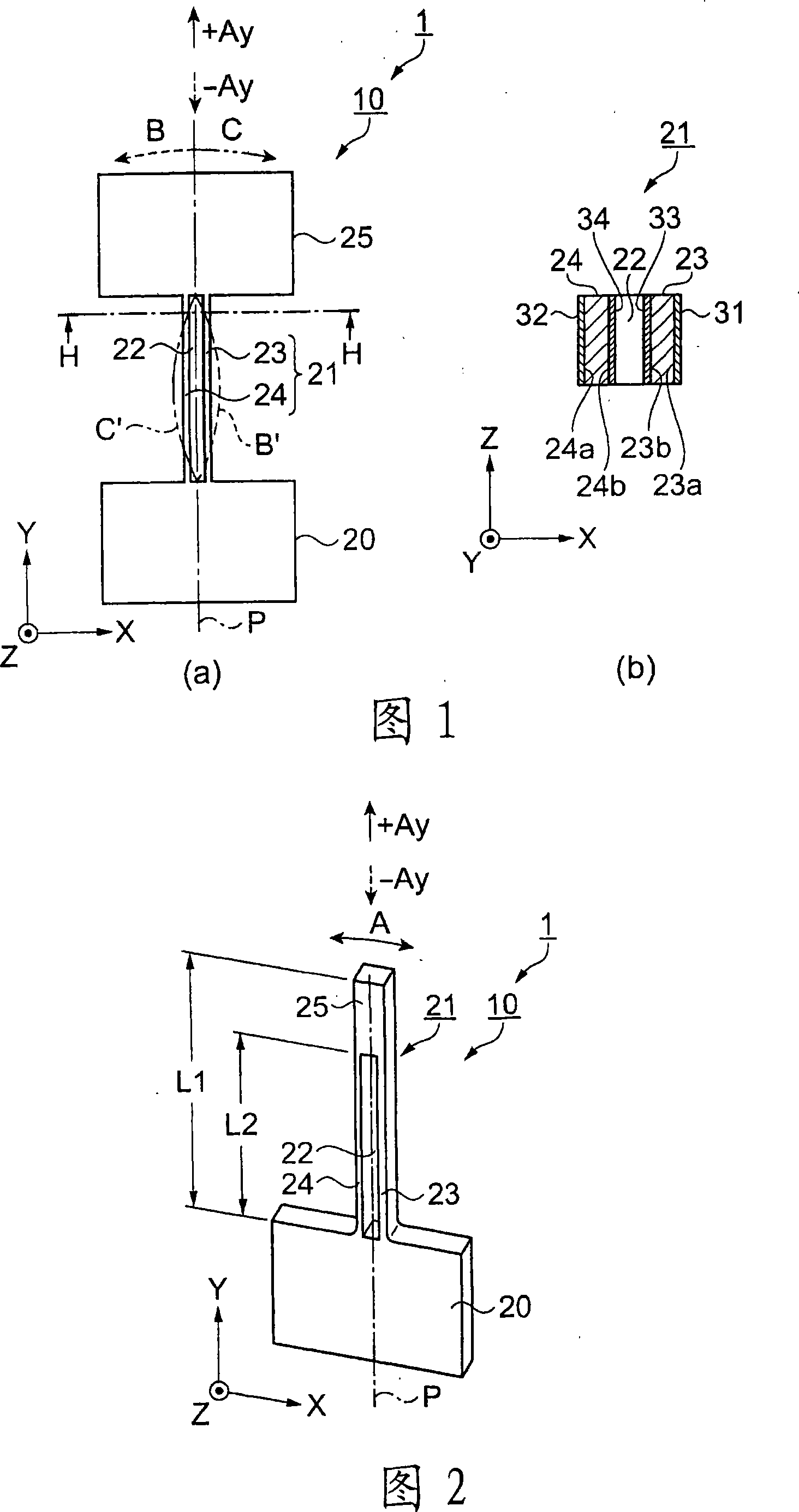
[0075] 1 shows an example of an acceleration sensor according to the first embodiment, (a) is a front view, and (b) is a cross-sectional view showing a H-H cross section of (a). In Fig. 1 (a), the acceleration sensor 1 is composed of a vibrating body 10. The vibrating body 10 has a base 20 fixed on a base (not shown), and extends from the end face of the base 20 and vibrates at a predetermined resonant frequency. The beam-shaped vibrating arm 21 flexurally vibrates in the planar direction.

[0076] The vibrating body 10 is formed of a piezoelectric material. As the piezoelectric material, lead titanate (PbTiO 3 ), lead zirconate titanate (PZT (registered trademark)), zinc oxide (ZnO), quartz, etc., but in this embodiment, a case of using quartz having excellent frequency temperature characteristics and a high Q value will be described as an example.

[0077] The vibrating body 10 is a Z-cut plate developed on the XY plane, and a simple beam-shaped vibrating arm 21 is formed ...

Deformed example 1

[0102] Next, an acceleration sensor according to Modification 1 of the first embodiment will be described with reference to the drawings. Modification 1 is characterized in that the vibrating body performs primary bending vibration with a single-end fixed structure. FIG. 2 is a perspective view showing the configuration of an acceleration sensor according to Modification 1. FIG. In FIG. 2 , the vibration body 10 serving as an acceleration sensor has the same shape as that of the first embodiment (see FIG. 1 ), except for the additional mass portion 25 . The additional mass part 25 is provided on the extension line of the vibrating arm 21 , and the vibrating arm 21 is divided into vibrating arm parts 23 and 24 by the through opening 22 .

[0103] The excitation electrodes 31 to 34 shown in FIG. 1 are provided on the side surfaces of the vibrating arm portions 23 and 24 . If excitation signals of opposite potentials are input from the oscillation circuit to excitation electrod...

Deformed example 2

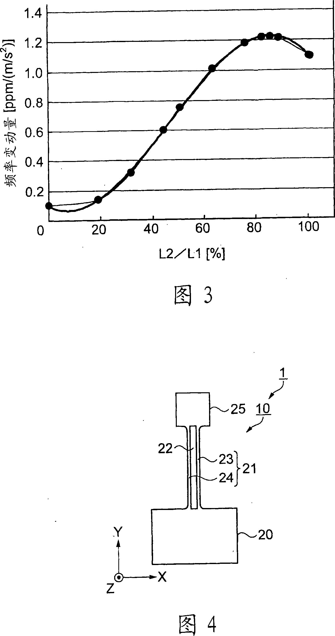
[0111] Next, an acceleration sensor according to Modification 2 of the first embodiment will be described with reference to the drawings. Modification 2 is characterized in that the free end of the vibrating arm is provided with a large additional mass portion capable of primary bending vibration. Therefore, the description will mainly focus on differences from the above-mentioned first embodiment (see FIG. 1 ). Common parts are given the same symbols as in the first embodiment.

[0112]FIG. 4 is a front view showing a vibrator according to this modification. In FIG. 4 , the beam-shaped vibrating arm 21 of the vibrating body 10 extends vertically in the Y-axis direction from the center of one side of the base 20 . A through-opening 22 is opened along the longitudinal direction (Y-axis direction) at the center of the vibrating arm 21 in the width direction (X-axis direction), and the through-opening 22 penetrates through the thickness direction (Z-axis direction).

[0113] T...


PUM


Abstract

The present invention provides a small and highly sensitive acceleration sensor. The acceleration sensor (1) is a vibrating body (10) composed of a base (20) fixed on a base and a beam-shaped vibrating arm (21) extending from the base and bendingly vibrating in a plane direction at a predetermined resonance frequency , wherein the vibrating arm has: a vibrating arm part (23, 24) that is divided in the central part in the width direction by a through opening (22) perpendicular to the vibration direction and set in the length direction; An additional mass part (25) with the same or greater mass as the base of the front end of the vibrating arm part; and excitation electrodes (31-34) arranged on the vibrating arm part, the vibrating arm is fixed by the base part and the additional mass part with pseudo double ends Structurally supported, the acceleration sensor detects a change in the resonance frequency of the vibrating body brought about by the inertial effect of the additional mass portion when acceleration is applied.

Description

technical field [0001] The present invention relates to an acceleration sensor that detects a change in the resonance frequency of a vibrating body when acceleration is applied. Background technique [0002] Conventionally, there is known an acceleration sensor (for example, refer to Patent Document 1), which is composed of a flexible spring, a resonator, and silicon having a vibrating mass suspended from a frame, and detects acceleration based on a frequency change of the resonator. , the flexible spring and the frame as well as the vibrating mass are made by structuring of small silicon chips. [0003] In addition, there is also known an acceleration sensor (for example, refer to Patent Document 2) that includes a piezoelectric vibrator composed of a cantilever whose one end is fixed on a silicon wafer substrate and whose other end is One end has a deformable free end; a piezoelectric element film formed on the surface of the cantilever; metal electrodes formed on both su...

Claims


Application Information

Patent Timeline
IPC IPC(8): G01P15/08G01P15/09G01P15/10
Inventor 西泽竜太田中雅子
Owner SEIKO EPSON CORP
Why Eureka
Try Eureka