Unpowered type air heat recovery device

A technology of recovery device and air heat, applied in heat recovery system, shielding with air flow, space heating and ventilation, etc., can solve the problems of low heat recovery efficiency, power consumption, large equipment and equipment, etc., and achieve significant energy saving Effective and economical, easy to process and transport, simple structure

Inactive Publication Date: 2008-04-30
赵耀华
View PDF6 Cites 35 Cited by
  • Summary
  • Abstract
  • Description
  • Claims
  • Application Information

AI Technical Summary

Problems solved by technology

[0006] Among them, the wheel-type heat recovery device alternates between two media, which cannot completely avoid cross-contamination. It is required that the gas flowing through must be harmless, and the equipment is relatively large, and it needs to consume a certain amount of kinetic energy; the plate heat exchanger device does not need transmission. The component has a simple structure and low cost, but it has very high requirements on the material of the partition, which needs to be replaced frequently, difficult to maintain, and the heat recovery efficiency is not high; the circulation pump in the water circulation heat recovery device consumes energy and heat The recovery efficiency is not high, and only in winter when the outdoor temperature is low can there be a good energy-saving effect; although the heat pump heat exchanger has high thermal efficiency and can recover a large amount of heat energy, it needs to be equipped with compressors, condensers, evaporators, etc. A series of supporting facilities, which itself consumes a lot of energy, and the equipment investment cost is high
Moreover, all the above-mentioned existing heat recovery devices must consume a certain amount of electric energy

Method used


Image

  • Unpowered type air heat recovery device
  • Unpowered type air heat recovery device
  • Unpowered type air heat recovery device

Examples


Embodiment Construction

[0033] The present invention will be further described below in conjunction with the accompanying drawings.

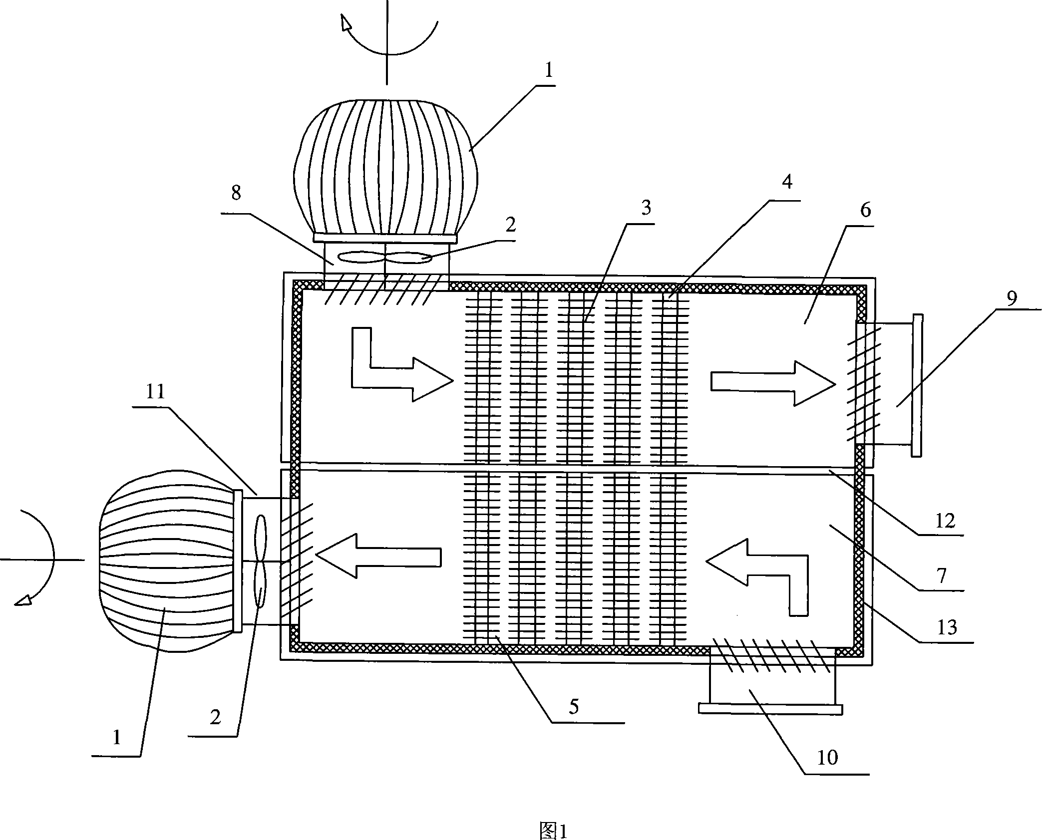
[0034] FIG. 1 is a schematic structural view of the air heat recovery device of the present invention.

[0035] In this embodiment, the heat recovery device divides the inner cavity of the housing 13 into two independent channels by the partition plate 12 provided in the middle, which are respectively the fresh air channel 6 and the exhaust air channel 7, wherein fresh air inlets 8 are arranged at both ends of the fresh air channel 6 and the fresh air outlet 9, the two ends of the exhaust passage 7 are provided with an exhaust air inlet 10 and an exhaust air outlet 11, wherein the fresh air outlet 9 and the exhaust air inlet 10 communicate with the room respectively, and the fresh air inlet 8 and the exhaust air outlet 11 communicate with the outdoor respectively, A wind cap 1 and a fan 2 are arranged at the outer ends of the fresh air inlet 8 and the exhaust air outle...


PUM


Abstract

The invention provides a powerless type air heat recollection device which is characterized in that the device at leased includes a fresh air channel used for bringing in fresh air and an air exhaustion channel to exhaust the indoor air, wherein, the two ends of the fresh air channel are respectively provided with an air inlet A communicated with the outside and an air outlet B communicated with the inside. The two ends of the air exhaustion channel are respectively provided with an air outlet A1 communicated with the outside and an air inlet B1 communicated with the inside; at least either of the air inlet A or air outlet A1 is provided with an air cap which includes a wind wheel and shaft, which are driven by the external wind power, and a fan which is driven by the shaft and can form a fixed air intake or exhaustion flow in the fresh air channel or the air exhaustion channel under the drive of the wind cap; the device also at least includes a heat exchanger which runs through the fresh air channel and the air exhaustion channel.

Description

technical field [0001] The present invention relates to air heat energy recovery technology, in particular to a non-powered air heat recovery device that utilizes the wind pressure principle of a non-powered hood to work. The heat recovery device can be independently miniaturized and applied to closed building spaces, and can also be used in large factory buildings Ventilation, suitable for heating, ventilation and air conditioning engineering technology. Background technique [0002] The quality of indoor air quality (abbreviated as IAQ) is very important to people's health. [0003] The most widely used method to improve indoor air quality is to introduce fresh air into the room, especially in a closed room equipped with an air conditioner, it is necessary to introduce a certain amount of fresh air to improve the air quality. However, the introduction of fresh air will inevitably increase the heat load of the air conditioning system and also affect the temperature of the ...

Claims


Application Information

Patent Timeline
Patent Type & Authority Applications(China)
IPC IPC(8): F24F12/00F28D15/04
CPCY02B30/16F24F12/006Y02B30/563Y02B30/56
Inventor 赵耀华刁彦华
Owner 赵耀华
Why Eureka
Try Eureka