
External rotor car permanent magneto

A technology of permanent magnet generator and external rotor, which is applied to synchronous motors with stationary armatures and rotating magnets, electromechanical devices, electrical components, etc., which can solve the problems of difficult heat dissipation, low production efficiency, and high rotor temperature. Achieve good heat dissipation effect, high production efficiency and low rotor temperature

Inactive Publication Date: 2008-04-30
梁昌勇
View PDF0 Cites 27 Cited by
  • Summary
  • Abstract
  • Description
  • Claims
  • Application Information

AI Technical Summary

Problems solved by technology

[0003] 1 The central part of the stator core has a material equivalent to the diameter of the rotor that cannot be utilized, resulting in a large waste
[0004] 2 The notch of the stator core faces inward, so it is difficult to insert wires, the production efficiency is low, and the cost is high
[0005] 3 Since the rotor is surrounded by the stator, the heat transferred from the stator to the rotor is not easy to dissipate, and the high temperature of the rotor will easily cause demagnetization of the permanent magnet and reduce the performance of the generator
[0006] If the vehicle permanent magnet generator structure is simply changed to a technical solution similar to the motorcycle magneto, that is, the structure of the inner stator and the outer rotor, the above problems do not seem to exist. However, due to the large current of the stator of the vehicle generator, the rectifier The voltage stabilizing device and the stator are extremely hot. Without forced heat dissipation, the motor cannot work normally, and it is difficult to install a conventional fan. Therefore, there is no permanent magnet generator product for vehicles with an inner stator and an outer rotor. Appear

Method used


Image

  • External rotor car permanent magneto
  • External rotor car permanent magneto
  • External rotor car permanent magneto

Examples


Embodiment Construction

[0024] Now in conjunction with accompanying drawing and embodiment the present invention will be further described:

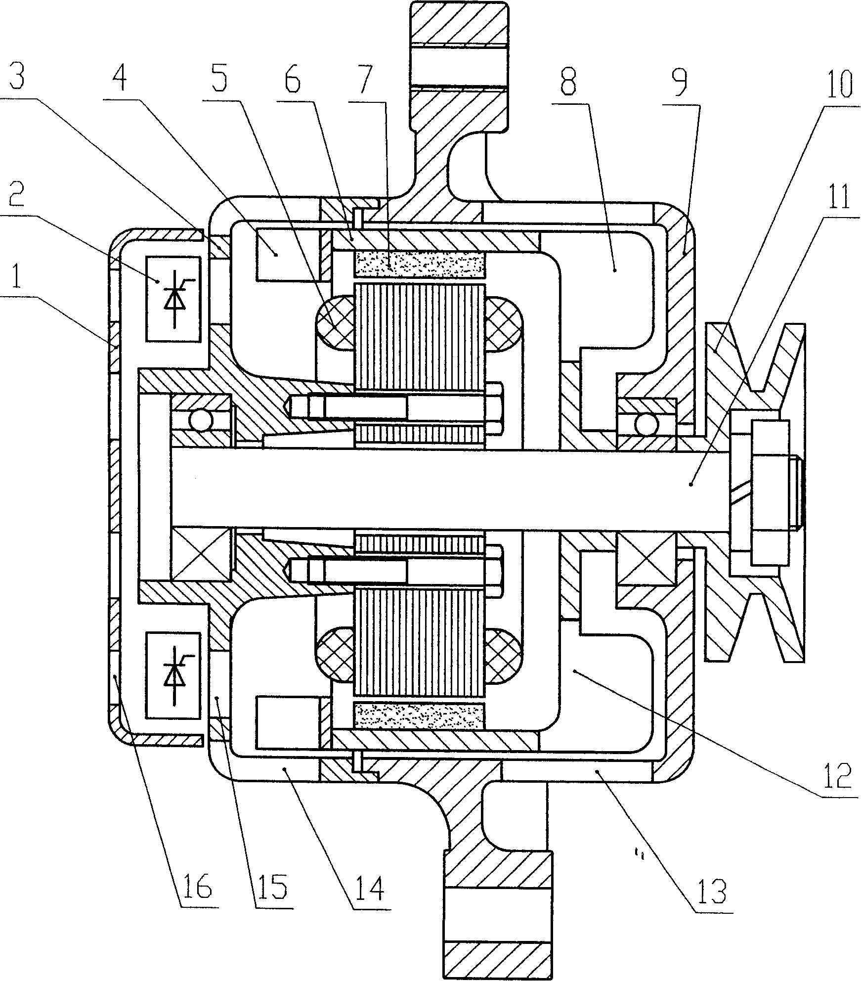
[0025] Permanent magnet generator structure of the present invention such as figure 1 As shown, it mainly consists of a cover 1, a rectifying and stabilizing device 2, a rear end cover 3, a centrifugal fan 4, a stator 5, a rotor casing 6, a tile-shaped permanent magnet 7, a front cover 9, a pulley 10, and a rotating shaft 11. The cover 1 has ventilation holes 16 in the axial direction, the rear end cover has ventilation holes 15 and radial ventilation holes 14 in the axial direction, and the front end cover only has ventilation holes 13 in the radial direction. The rotor shell 6 and the stator 5 are installed on the front cover 9 and the rear end cover 3, the stator 5 is tightly connected to the rear end cover 3, and the lead wire of the stator winding passes through the rear end cover 3 to connect with the rectification and voltage stabilization device 2, and ...


PUM


Abstract

An external-rotor type permanent-magnet generator for vehicles: a rotor and a stator are both mounted in a housing which consists of a front end cover and a rear end cover; the stator is firmly arranged on the rear end cover; the permanent-magnet rotor is positioned outside the stator; a centrifugation fan is mounted on the rotor in the rear end of the rotor; the permanent-magnet rotor is composed of a rotor case and a tile-shaped permanent magnet; the front end of the rotor case comprises a vent hole; a centrifugation fan is exposed to mount in the vent hole. During operation, the rotor is driven to rotate via an engine, so that two cooling air circuits will be formed inside the motor: one circuit is a cooling air circuit formed by the centrifugation fan on the rear end of the rotor; the circuit is mainly used to cool the rectification voltage stabilizer; the other circuit is a cooling air circuit that is formed with the rotor centrifugation fan exposed out of the rotor housing; the circuit mainly adapts to cool the rectification voltage stabilizer and the stator. Compared with the prior art, the invention has advantages of high utilization rate of iron core materials, convenient stator coiling, simultaneous effects with the two centrifugation fans, perfect heat radiation effects, low temperature of the stator and the rectification voltage stabilizer, and reliable operation.

Description

technical field [0001] The invention relates to a permanent magnet generator for vehicles, which can supply power for electrical appliances on the vehicle and charge batteries. Background technique [0002] The existing permanent magnet generators for vehicles all adopt the structure of outer stator and inner rotor. The problems of this structure are as follows: [0003] 1 The central part of the stator core has a material equivalent to the diameter of the rotor that cannot be utilized, resulting in a large waste. [0004] 2 The notch of the stator core faces inward, so it is difficult to insert wires, the production efficiency is low, and the cost is high. [0005] 3 Since the rotor is surrounded by the stator, the heat transferred from the stator to the rotor is not easy to dissipate, and the high temperature of the rotor will easily cause demagnetization of the permanent magnet and reduce the performance of the generator. [0006] If the vehicle permanent magnet generat...

Claims


Application Information

Patent Timeline
IPC IPC(8): H02K1/27H02K21/22H02K21/02H02K9/06H02K5/04H02K5/20
Inventor (发明人请求不公布姓名)
Owner 梁昌勇
Features
  • Generate Ideas
  • Intellectual Property
  • Life Sciences
  • Materials
  • Tech Scout
  • Unparalleled Data Quality
  • Higher Quality Content
  • 60% Fewer Hallucinations
Learn More