Stacked type solid electrolytic capacitor and method for manufacturing same

A solid electrolysis and capacitor technology, applied in the direction of solid electrolytic capacitors, electrolytic capacitors, capacitors, etc., can solve the problems of increased load on the anode terminal 52, deviation of connection strength, poor electrolytic capacitors, etc., and achieve good energization status, increased strength, Mitigate adverse effects of LC

Active Publication Date: 2008-05-07
SANYO ELECTRIC CO LTD +1
View PDF1 Cites 10 Cited by
  • Summary
  • Abstract
  • Description
  • Claims
  • Application Information

AI Technical Summary

Problems solved by technology

In addition, the variation in connection strength due to welding also increases
In view of these circumstances, there is a problem that LC failure often occurs in multilayer solid electrolytic capacitors
In addition, only four capacitor elements 46 are stacked in the multilayer solid electrolytic capacitor shown in FIG.
[0008] In addition, in the above-mentioned multilayer solid electrolytic capacitor shown in FIG. 17, although the above-mentioned problems are alleviated to some extent, since there is only one anode terminal 52, the load applied to the anode terminal 52 increases.
As a result, it is difficult to solve the above-mentioned problems due to the increased mechanical stress

Method used


Image

  • Stacked type solid electrolytic capacitor and method for manufacturing same
  • Stacked type solid electrolytic capacitor and method for manufacturing same
  • Stacked type solid electrolytic capacitor and method for manufacturing same

Examples


Deformed example 1

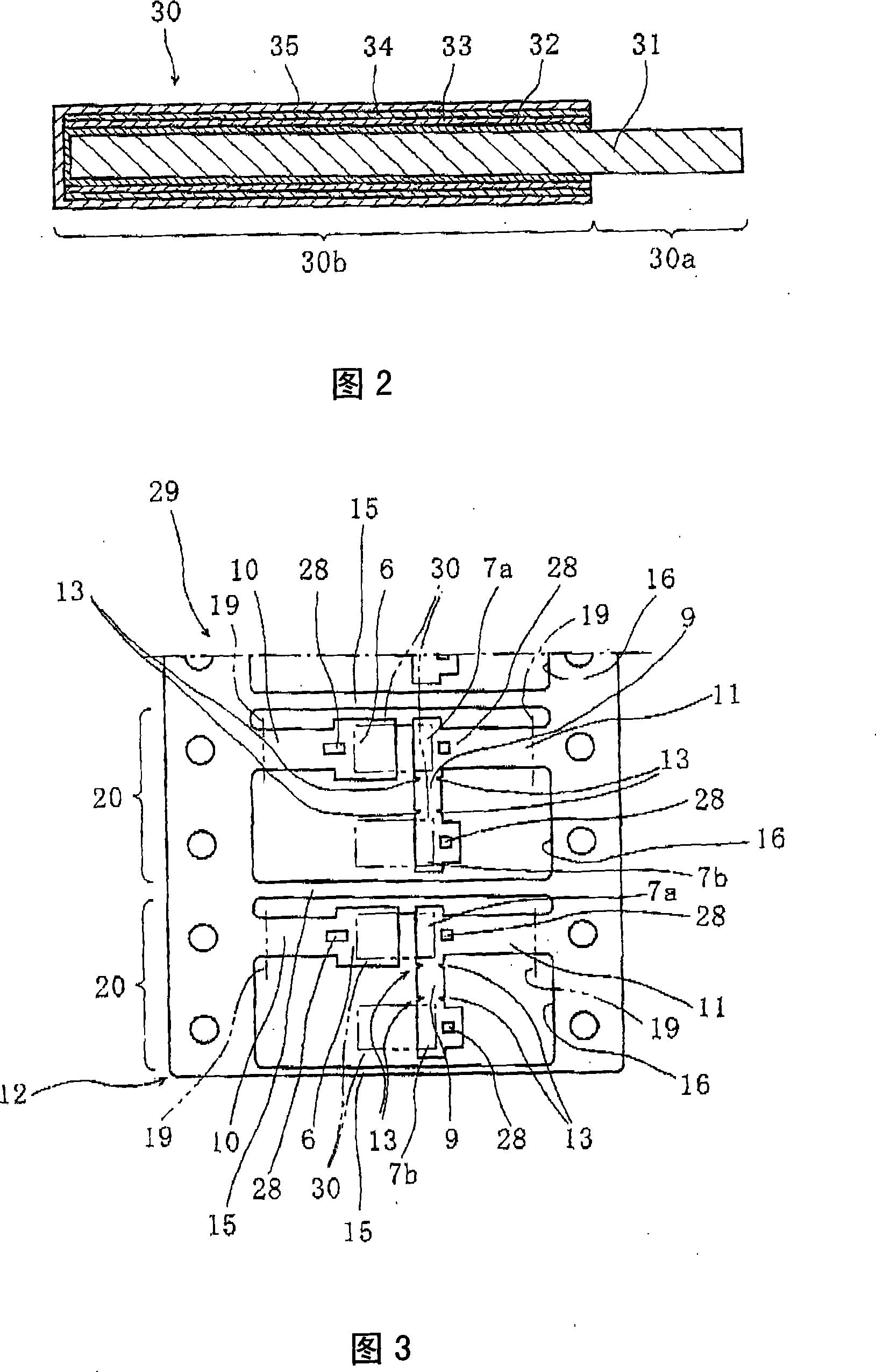
[0079] In the lead frame 12 shown in FIG. 7 , the configuration is the same as that of the above-mentioned best mode except that the number of cathode mounting portions 6 corresponding to the number of anode mounting portions 7 b is provided. In addition, the same code|symbol is attached|subjected to the member which has the same function as the above-mentioned best mode. Specifically, the cathode attachment portion 6 has the same juxtaposition structure as the anode attachment portions 7a, 7b, and is arranged in parallel at predetermined intervals and in the same shape. With regard to such lead frame 12, as shown in FIG. Part 6 is electrically connected.

[0080] By employing such a structure, the anode and the cathode of the capacitor element 30 can be stably blocked when the capacitor element 30 is laminated and when the lead frame 12 is bent.

[0081] In addition, as shown in FIG. 9, the cathode mounting parts 6, 6 are also connected by the connection part 21 similarly t...

Deformed example 2

[0083] As shown in FIG. 10, except that a notch 13a is provided between the anode mounting portions 7a, 7b of the lead frame 12, the configuration is the same as the above-mentioned best mode.

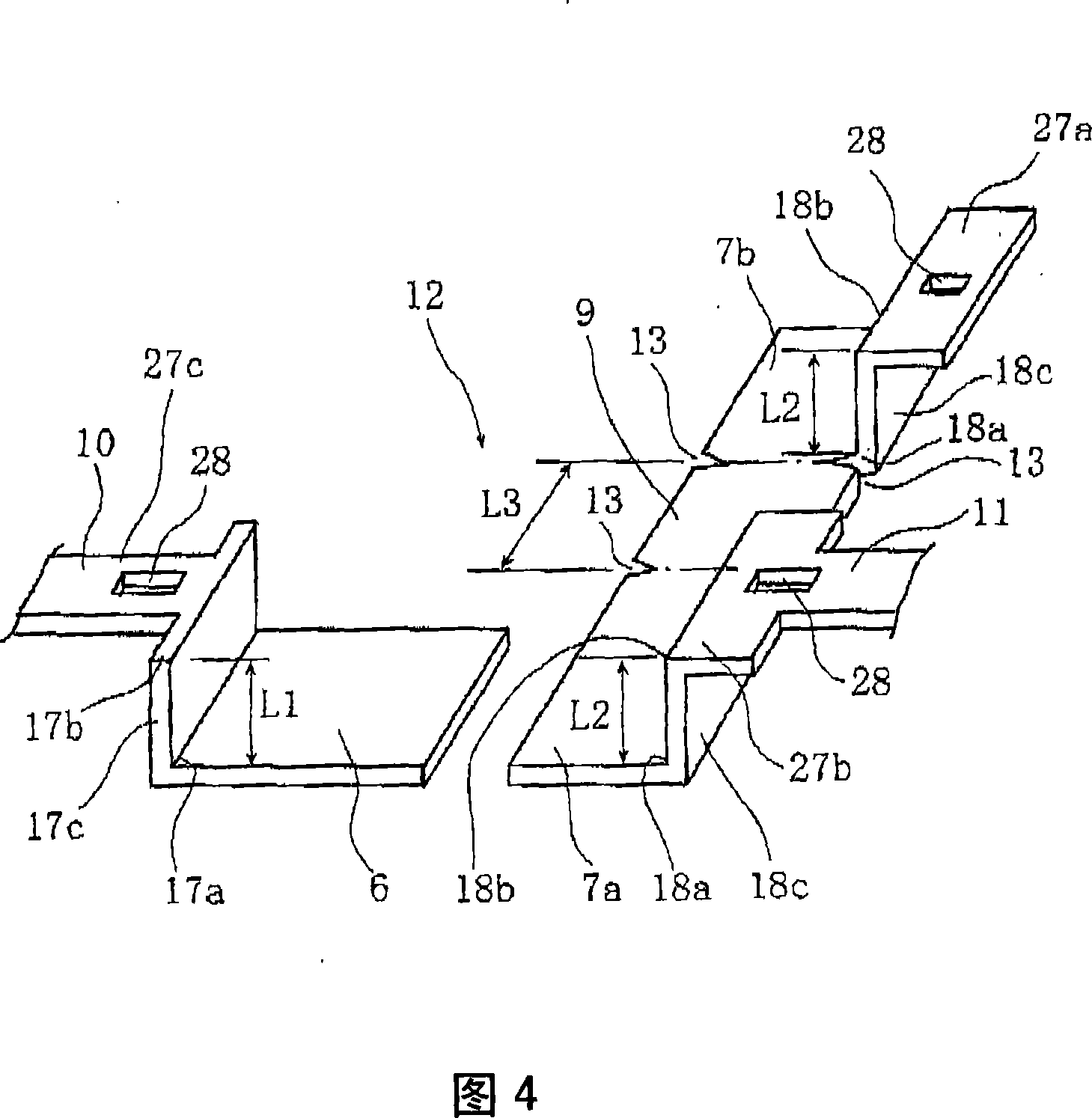
[0084] In such a lead frame 12, the laminated solid electrolytic capacitor can be fabricated by bending it upside down, in contrast to the above-mentioned best mode, so that the anode mounting part 7a and the anode mounting part 7b can pass through an extremely short (with the two The total thickness of the two anode mounting parts 7a, 7b is equal to the length) of the connecting part 9.

[0085] In addition, in the above configuration, although a gap is generated between one capacitor element 30 group and the cathode mounting portion 6, as shown in FIGS. 11 and 12, by interposing the conductive adhesive 14 between the gaps, the The cathode mounting part 6 is electrically connected to the cathode part 30b adjacent to the cathode mounting part 6 .

Deformed example 3

[0087] As shown in Figure 13, except that one more cathode mounting part 6 and anode mounting part 7b are provided in the lead frame (that is, the cathode mounting part and the anode mounting part are provided three by three), the structure is the same as that of the above-mentioned modification 1. .

[0088] Specifically, as shown in FIG. 14 , one anode mounting portion 7 b is folded in the same direction as the first modification, and the other anode mounting portion 7 b is folded in the opposite direction to the first modification. According to such a configuration, more capacitor elements 30 can be mounted.

[0089] In addition, the continuous number of the three anode mounting parts 7a, 7b can be increased within the range allowed by the design as required, and can be 4 or 5. In this case, the bending direction is reversed sequentially.

[0090] (something else)

[0091] (1) In the above method, the notch 13 that is easy to bend the lead frame 12 is formed at the bound...


PUM


Abstract

A solid electrolytic capacitor has a structure wherein a capacitor element (30) is arranged by being stacked, and an anode section (30a) is fixed by being welded on anode mounting planes of anode mounting sections (7a, 7b) provided on an anode terminal. The solid electrolytic capacitor is characterized in that the two anode mounting sections (7a, 7b) are provided, the anode mounting sections (7a, 7b) are arranged in parallel, and the adjacent anode mounting sections (7a, 7b) are mutually connected by a connecting section (9).

Description

technical field [0001] The present invention relates to a laminated solid electrolytic capacitor and its manufacturing method. Background technique [0002] The multilayer solid electrolytic capacitor according to the present invention can be used, for example, as a chip capacitor mounted on a printed circuit board. For such laminated solid electrolytic capacitors, electrolytic capacitors using dielectric polymers such as TCNQ complex salts or polypyrrole, polythiophene, polyfuran, and polyaniline as solid electrolytes have attracted attention. Among the demands, at present, solid electrolytic capacitors are required to be smaller in size and larger in capacity. In addition, in order to achieve high-speed signal processing such as CPUs and low power consumption, the technical trend of high frequency and high current has been strengthened, and low ESR of capacitors is strongly required. [0003] Here, the conventional multilayer solid electrolytic capacitor is produced by t...

Claims


Application Information

Patent Timeline
Patent Type & Authority Applications(China)
IPC IPC(8): H01G9/004H01G9/00H01G9/04H01G9/15
CPCH01G9/26H01G9/012H01G9/08H01G9/06H01G9/14H01G9/15H01G9/00H01G9/04
Inventor 堀尾和丰有森慎二
Owner SANYO ELECTRIC CO LTD
Why Eureka
Try Eureka