Generating discrete gas jets in plasma arc torch applications

A plasma and jet flow technology, applied in the direction of plasma, plasma welding equipment, electrical components, etc., can solve the problems of instability of plasma gas flow, destruction of plasma gas flow, poor processing of workpieces, etc., to achieve cooling improvement, Reduced surface roughness and waviness, effective workpiece machining

Active Publication Date: 2008-05-07
HYPERTHERM INC
View PDF1 Cites 8 Cited by
  • Summary
  • Abstract
  • Description
  • Claims
  • Application Information

AI Technical Summary

Problems solved by technology

Due to this impact, the ionized plasma gas flow may be disrupted (e.g. generating plasma gas flow instabilities), which may result in poorly processed workpieces

Method used


Image

  • Generating discrete gas jets in plasma arc torch applications
  • Generating discrete gas jets in plasma arc torch applications
  • Generating discrete gas jets in plasma arc torch applications

Examples


Embodiment Construction

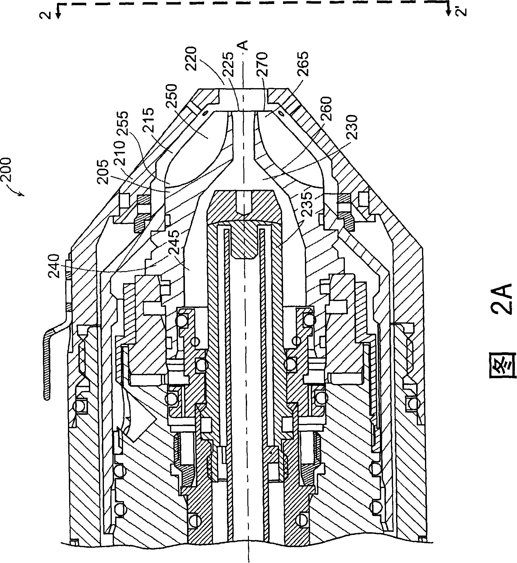
[0036] Figure 2A depicts an exemplary embodiment of a fluid passage provided within a nozzle of the present invention. FIG. 2 shows a torch tip 200 comprising a nozzle 205 having a shield 210 mounted coaxially therewith along the longitudinal axis A and spaced apart. Both nozzle 205 and shield 210 may be made of electrically conductive material. In some embodiments, nozzle 205 and shield 210 are made of the same conductive material. In other embodiments, nozzle 205 and shield 210 are made of different conductive materials. Examples of conductive materials suitable for use in torch tip 200 include, but are not limited to, pure copper, aluminum, or brass. In the illustrated embodiment, the nozzle 205 and shield 210 are mounted in spaced relation to each other forming an auxiliary fluid passage 215 therebetween.

[0037] During workpiece processing, a fluid such as an auxiliary gas may flow along auxiliary fluid passage 215 and ultimately from torch tip 200 through outlet port...


PUM


Abstract

The present invention is generally directed to a nozzle for a plasma torch, the nozzle having a rear portion that defines at least a portion of a plasma chamber and a front portion that includes a first end and a second end. The first end is adjacent the rear portion, and the second end defines a plasma exit portion. One or more fluid passageways are disposed within the front portion and extend from the first end to the second end. The fluid passageways have passageway exit portions that provide one or more discrete jets of a secondary fluid to surround a plasma jet that is ejected from the plasma exit portion. Features of the invention include faster cutting, thicker workpiece piercing capability, reduced noise, improved arc stability, and increased consumable life, all of which improve productivity associated with plasma arc torch workpiece processing.

Description

technical field [0001] The present invention relates generally to the operation of plasma arc torches, which can be used for machining workpieces, such as cutting, piercing, or marking metal workpieces, and in particular to improvements in plasma jets. Background technique [0002] Currently, plasma arc torches are widely used for machining workpieces, such as cutting, piercing, and / or marking metallic materials (ie, elemental metals, metal alloys, etc.). A plasma arc torch generally includes an electrode mounted within the body of the torch (i.e., the torch body), a nozzle with a plasma exit portion (sometimes called an exit hole or port), an electrical connection, and a cooling fluid , a fluid path for a protection fluid and an arc control fluid, a rotating ring for controlling a fluid flow pattern in a plasma chamber formed between an electrode and a nozzle, and a power source. The torch produces a plasma arc, which is a constricted jet of ionized plasma gas (ie, a strea...

Claims


Application Information

Patent Timeline
Patent Type & Authority Applications(China)
IPC IPC(8): H05H1/34
CPCH05H2001/3478H05H2001/3468H05H2001/3457B23K10/00H05H1/3405H05H1/34H05H1/3457H05H1/3468H05H1/3478
Inventor D·J·库克S·M·利伯德J·W·林赛Z·段
Owner HYPERTHERM INC
Why Eureka
Try Eureka