
Equipment and method for measuring material damping factor

A material damping and factor technology, applied in measurement devices, analytical materials, instruments, etc., can solve the problems of high cost of measurement devices, complex testing devices, and high testing costs, and achieve the effects of simple measurement methods, shortened measurement time, and convenient operation.

Active Publication Date: 2008-05-14
GUOBIAO BEIJING TESTING & CERTIFICATION CO LTD
View PDF0 Cites 5 Cited by
  • Summary
  • Abstract
  • Description
  • Claims
  • Application Information

AI Technical Summary

Problems solved by technology

At present, the method of measuring the damping factor of materials mainly adopts the method of bending resonance. The test device for this measurement method is relatively complicated, and generally consists of a signal generator, an electromagnetic transducer, a frequency meter, an oscilloscope, an amplifier, and a recording and indicating instrument.
In the test, each component needs to be adjusted and proofread, which is cumbersome, takes a long time to operate, and is prone to systematic errors
High cost of measurement setup and high cost of testing

Method used


Image

  • Equipment and method for measuring material damping factor
  • Equipment and method for measuring material damping factor
  • Equipment and method for measuring material damping factor

Examples


Embodiment Construction

[0020] The structure of the device for measuring the material damping factor and the method for implementing the measurement designed in the present invention will be further described below according to the drawings and specific embodiments.

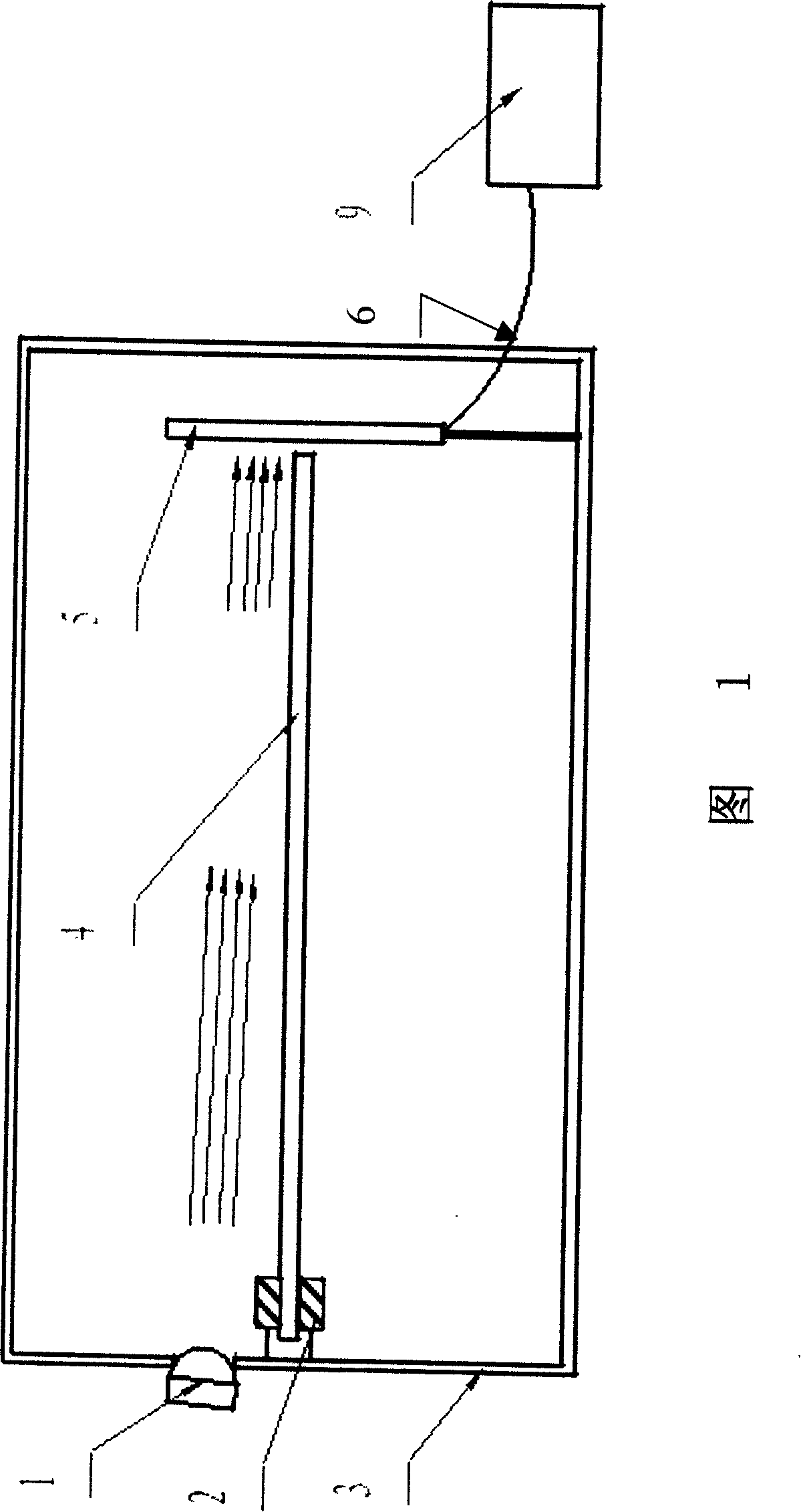
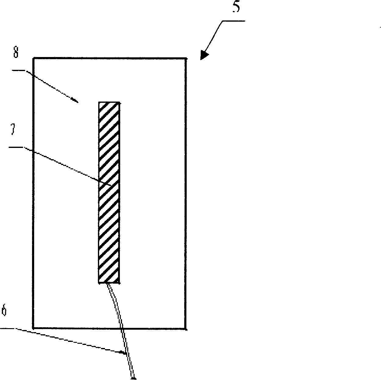
[0021] The equipment for measuring the damping factor of a material as shown in Figure 1 is composed of a measuring device and a data processing device 9. The measuring device is mainly composed of a light source 1, a fixture 2, a dark box 3, and a photocell sensor 5. The fixture 2 and the photocell sensor 5 are located in the dark box 3. Inside, the light source 1 is located on the side wall of the dark box 3, which is a constant white light source, illuminating in the direction of the photocell sensor 5 in the dark box 3. The photocell sensor 5 is installed on the side of the dark box opposite to the light source. figure 2 As shown, it is composed of a signal lead wire 6, a photovoltaic cell 7, and a back plate 8. The photovoltaic cell 7...


PUM


Abstract

The invention relates to a device for measuring the damping factor of a material and a method for using the device to measure, belonging to the category of instrument measurement. The equipment is composed of a measuring device and a data processing device. The measuring device is mainly composed of a dark box, a light source, a fixture, and a photocell sensor. The fixture and the photocell sensor are located in the dark box. The light source is located on the side wall of the dark box and illuminates the photocell sensor in the dark box. Installed in the dark box opposite to the light source, the photocell sensor is connected with a signal lead-out line, the fixture and the light source are located on the same side, which corresponds to the middle position of the photocell sensor; the data processing device is mainly composed of A / D converter and single-chip microcomputer, A / D The converter is connected with the single-chip microcomputer, and the signal lead-out line of the photocell sensor is connected with the A / D converter. The above-mentioned device measures the material damping factor by means of photoelectric signal conversion. The invention has quick operation and convenient measurement, and can be widely used in the measurement field of solid materials.

Description

(1) Technical field [0001] The invention relates to a device for measuring the damping factor of a material through photoelectric signal conversion and a method for using the device to measure, and belongs to the category of instrument measurement. (2) Background technology [0002] Damping factor is an important parameter reflecting the damping characteristics of materials. At present, the measurement of material damping factor mainly adopts the method of bending resonance. The testing device for this measurement method is more complicated, and generally consists of a signal generator, an electromagnetic transducer, a frequency meter, an oscilloscope, an amplifier, and a recording indicator instrument. In the test, each component needs to be adjusted and proofread, which is cumbersome, takes a long time to operate, and is prone to system errors. The cost of measuring devices is high, and so is the cost of testing. (3) Summary of the invention [0003] The purpose of the present...

Claims


Application Information

Patent Timeline
Patent Type & Authority Applications(China)
IPC IPC(8): G01N19/00G01B11/00
Inventor 唐海波
Owner GUOBIAO BEIJING TESTING & CERTIFICATION CO LTD
Learn More