Stepwise magnetic force hoisting type reactor control rod driving mechanism

A driving mechanism and reactor technology, which is applied in the control of nuclear reactions, reactors, and greenhouse gas reduction, etc., can solve the problems of difficulty in guaranteeing parallelism, poor impact resistance, and complex structure of parallel four-bar mechanisms, so as to improve safety and reliability. The effects of improved durability, increased wear life, and reduced chance of hook tooth breakage

Active Publication Date: 2008-05-14
SICHUAN HUADU NUCLEAR EQUIP MFR
View PDF0 Cites 33 Cited by
  • Summary
  • Abstract
  • Description
  • Claims
  • Application Information

AI Technical Summary

Problems solved by technology

However, the existing magnetic lifting type drive mechanism has the following defects: 1. Since there are three small Ω sealing welds on the pressure-resistant shell assembly, the weld positions are respectively between the seal shell and the drive mechanism socket on the top cover of the pressure vessel (lower position), between seal housing and travel sleeve (middle position) and between travel sleeve and end plug (upper position)
2. Since the control rod drive mechanism usually adopts single-toothed claw or four-toothed claw, the single-toothed claw type drive mechanism has the disadvantages

Method used


Image

  • Stepwise magnetic force hoisting type reactor control rod driving mechanism
  • Stepwise magnetic force hoisting type reactor control rod driving mechanism

Examples


Embodiment Construction

[0024] The present invention will be further described below in conjunction with accompanying drawing and embodiment:

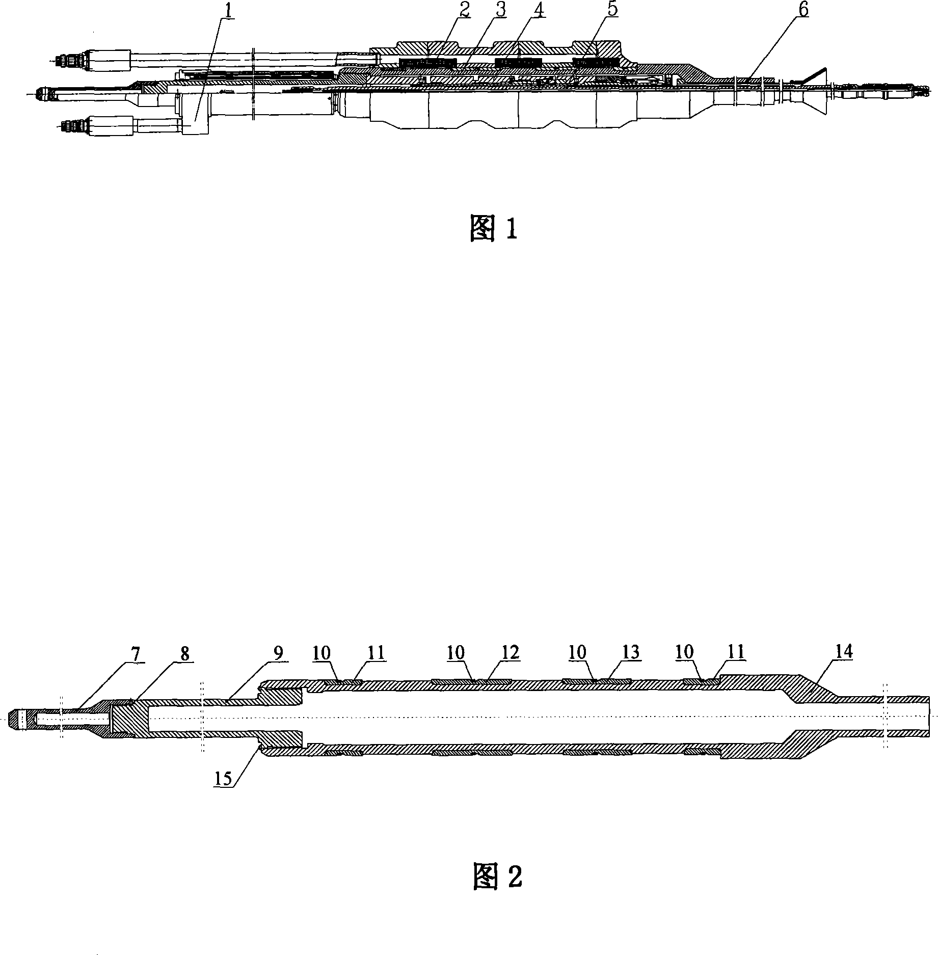
[0025] As shown in Figure 1, the step-by-step magnetic lifting type reactor control rod drive mechanism of the present invention consists of a rod position detector assembly 1, a coil assembly 2, a pressure shell assembly 3, a claw assembly 4, a drive rod assembly 5 and a heat insulation The set consists of 6 components. The whole mechanism is directly installed vertically on the top cover of the reactor pressure vessel. The rod position detector assembly 1 is set on the stroke sleeve 9 of the pressure-resistant shell assembly 3. When the driving mechanism is running, it can give the actual position signal of the driving rod. Rod time; the coil assembly 2 is set outside the sealing shell 14 of the pressure shell assembly 3, and the electromagnetic attraction generated by it provides a power source for the operation of the drive mechanism; the claw assembly 4...


PUM


Abstract

The invention provides a marching type and magnetic jacking reactor control rod drive mechanics, which comprises a rod position detector component, a coil component, a pressure shell component, a knuckle component, a driving rod component, a heatproof lagging component and the like. The whole mechanism is vertically mounted on a top cover of a reactor pressure vessel directly, wherein the pressure shell component consists of a hoisting connector, a travel sleeve and a hermetic case. The travel sleeve of the pressure shell component is an integral blind tube with a blocked upper end and the hermetic case is an integral structure composed of a tube socket of the driving mechanism on the top cover of the reactor pressure vessel, and the hermetic case. The knuckle component is composed of two identical knuckle teeth arranged side by side, the distance between the two knuckle teeth is equal to the teeth space of the driving rod component, and the two sides of the flute between the two knuckle teeth are of transitional circular arc shape. The invention greatly reduces the leakage possibility of the pressure shell of the reactor control rod drive mechanics, and greatly improves the wear resistance, the reliability and the service life of the reactor control rod drive mechanics.

Description

technical field [0001] The invention belongs to a reactor control rod driving mechanism of a pressurized water reactor nuclear power plant, in particular to a step-by-step magnetic lifting type reactor control rod driving mechanism. Background technique [0002] The reactor control rod drive mechanism is the servo mechanism of the reactor control and protection system. It is the actuator of the reactor control system and protection system. or power off and drop rods to complete the function of adjusting reactor reactivity or accidental safety shutdown; the control rod drive mechanism completes the start-up, power adjustment, maintenance power, The safety and reliability of safety shutdown under shutdown and accident state directly affect the safety and operation of the reactor. [0003] At present, there are three main types of control rod drive mechanisms used in nuclear power reactors and pressurized water reactor nuclear power plant reactors: [0004] ·Reluctance motor-...

Claims


Application Information

Patent Timeline
IPC IPC(8): G21C7/12
CPCY02E30/39Y02E30/30
Inventor 李红鹰杨柯孙林赵晓刚彭航胥春燕杨方亮陈西南杨晓晨余志伟王亚曦李金贤王福娣
Owner SICHUAN HUADU NUCLEAR EQUIP MFR
Why Eureka
Try Eureka