Power supply control method and power supply device for electron beam generating system of electron beam bombardment furnace

A technology of electron beam bombardment and generation system, which is applied in the field of power supply device and electron beam generation system power control of electron beam bombardment furnace. The effect of reducing harmonic components and improving utilization

Inactive Publication Date: 2008-05-14
GUILIN UNIV OF ELECTRONIC TECH
View PDF0 Cites 6 Cited by
  • Summary
  • Abstract
  • Description
  • Claims
  • Application Information

AI Technical Summary

Problems solved by technology

[0009] 1) The harmonic amplitude of the input current on the AC side is large, causing serious pollution to the power grid and forming a "public nuisance" of electricity;
[0010] 2) Phase-shift voltage regulation increases the current lag phase angle, and the power factor becomes lower;
[0011] 3) In order to ensure the adjustment volume requirements, the main transformer capacity design has a large margin, the utilization rate is low, the loss of the main transformer is large, and the operating efficiency is not high;
[0012] 4) The input voltage waveform of the main transformer is a non-sinusoidal wave, and the hi

Method used


Image

  • Power supply control method and power supply device for electron beam generating system of electron beam bombardment furnace
  • Power supply control method and power supply device for electron beam generating system of electron beam bombardment furnace
  • Power supply control method and power supply device for electron beam generating system of electron beam bombardment furnace

Examples


Example Embodiment

[0043] The power control method of the electron beam generation system of the electron beam bombardment furnace of the present invention is as follows:

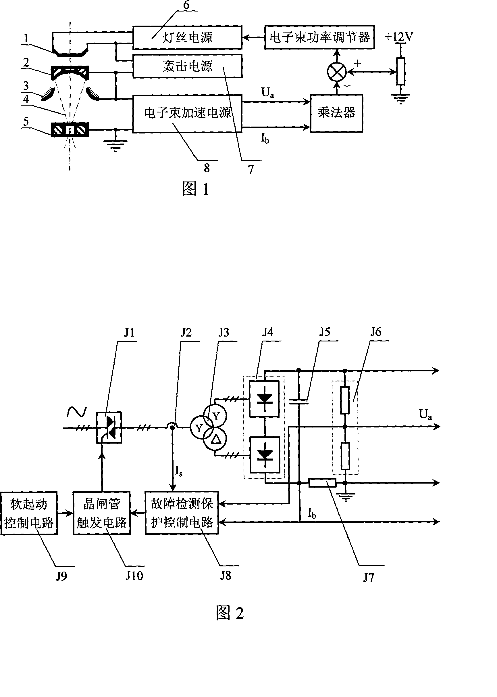
[0044] The electron beam acceleration power supply adopts thyristor soft start and soft stop to realize the smooth rise and fall of the acceleration voltage during the start and stop process; the acceleration power supply of the melting process adopts open-loop control, and the input terminal of the booster main transformer is directly connected to the three-phase mains, and the input voltage is a complete three-phase power supply. Phase sine wave, after boosting, the uncontrollable DC high voltage is obtained by six-phase twelve-pulse full-wave rectification. The input current waveform of the booster main transformer is approximately sine wave; the DC high voltage output terminal is connected with a sampling circuit to output accelerated voltage sampling respectively Signal U a And the electron beam sampling signal I b . The inp...


PUM


Abstract

The invention is a control method and a power device used in a process that an electron beam bombards furnace electron beam to produce system power. The method is able to speed up a power open-loop control, and is able to speed up a power pressure and electron beam current sampling signal as a control signal of bombardment power supply, filament power supply and electron beam power, and the electron beam power is steady and easy of being adjusted under a coordinated operation of the three powers. A harmonic is small and has a rather small effect on an electric fence, and power factors and efficiency of the equipment are rather high, and the operation is reliable. A main transformer of an accelerator power supply in the power device is side-connected with three-phase voltage once, and an output terminal is connected with an accelerating voltage bleeder circuit and an electron beam current sampling resistance to output sampling signals. The accelerator power supply further is connected with a thyristor device and a trigger circuit, a soft start controlling circuit, a fault-detecting protection controlling circuit etc. The bombardment power supply comprises a PWM, a bombardment inverter, a bombardment transformer and a bombardment power supply adjustor etc. The filament power supply and the beam power controlling circuit are composed of the PWM, a filament inverter, a filament transformer, a bean power setting potentiometer, a multiplier, a beam power adjustor, a filament power supply adjustor etc.

Description

(1) Technical field [0001] The invention relates to an electron beam electric heating device, in particular to a power control method and a power supply device for an electron beam generating system of an electron beam bombardment furnace. (2) Background technology [0002] The electron beam bombardment furnace is an electrothermal equipment that uses the heat energy generated when high-speed electrons bombard the charge for melting and heating. Compared with other vacuum melting furnaces, it has high power density and can be used for smelting and refining precious, rare and refractory metals. The vacuum degree in the furnace is high, and it is easy to prepare various high-purity materials or Special alloys and used for smelting high-quality special steel and titanium waste recycling, etc. In addition, it also has the advantage of no refractory material pollution to the charge. The development direction of the electron beam bombardment furnace is high power and multiple gun...

Claims


Application Information

Patent Timeline
IPC IPC(8): H05B7/144C22B4/00C22B9/00
CPCY02P10/20Y02P10/25
Inventor 韦寿祺莫金海
Owner GUILIN UNIV OF ELECTRONIC TECH
Why Eureka
Try Eureka