Covering type composite vacuum electroosmosis, method for forced ramming reinforcing foundation and device thereof

A covered and electroosmotic technology, which is applied in infrastructure engineering, soil protection, construction, etc., can solve the problems of not being able to prevent rainwater recharge, high vacuum attenuation of vacuum system, and being easily disturbed by weather factors, etc., to solve the problem of weather Interference of factors, easy construction and operation, and the effect of widening the selection range

Inactive Publication Date: 2008-05-21
陈江涛 +3
View PDF1 Cites 10 Cited by
  • Summary
  • Abstract
  • Description
  • Claims
  • Application Information

AI Technical Summary

Problems solved by technology

The patent has the disadvantages that the electroosmosis process is only used for electroosmosis and vacuum precipitation at a single level, w

Method used


Image

  • Covering type composite vacuum electroosmosis, method for forced ramming reinforcing foundation and device thereof
  • Covering type composite vacuum electroosmosis, method for forced ramming reinforcing foundation and device thereof
  • Covering type composite vacuum electroosmosis, method for forced ramming reinforcing foundation and device thereof

Examples


Embodiment 1

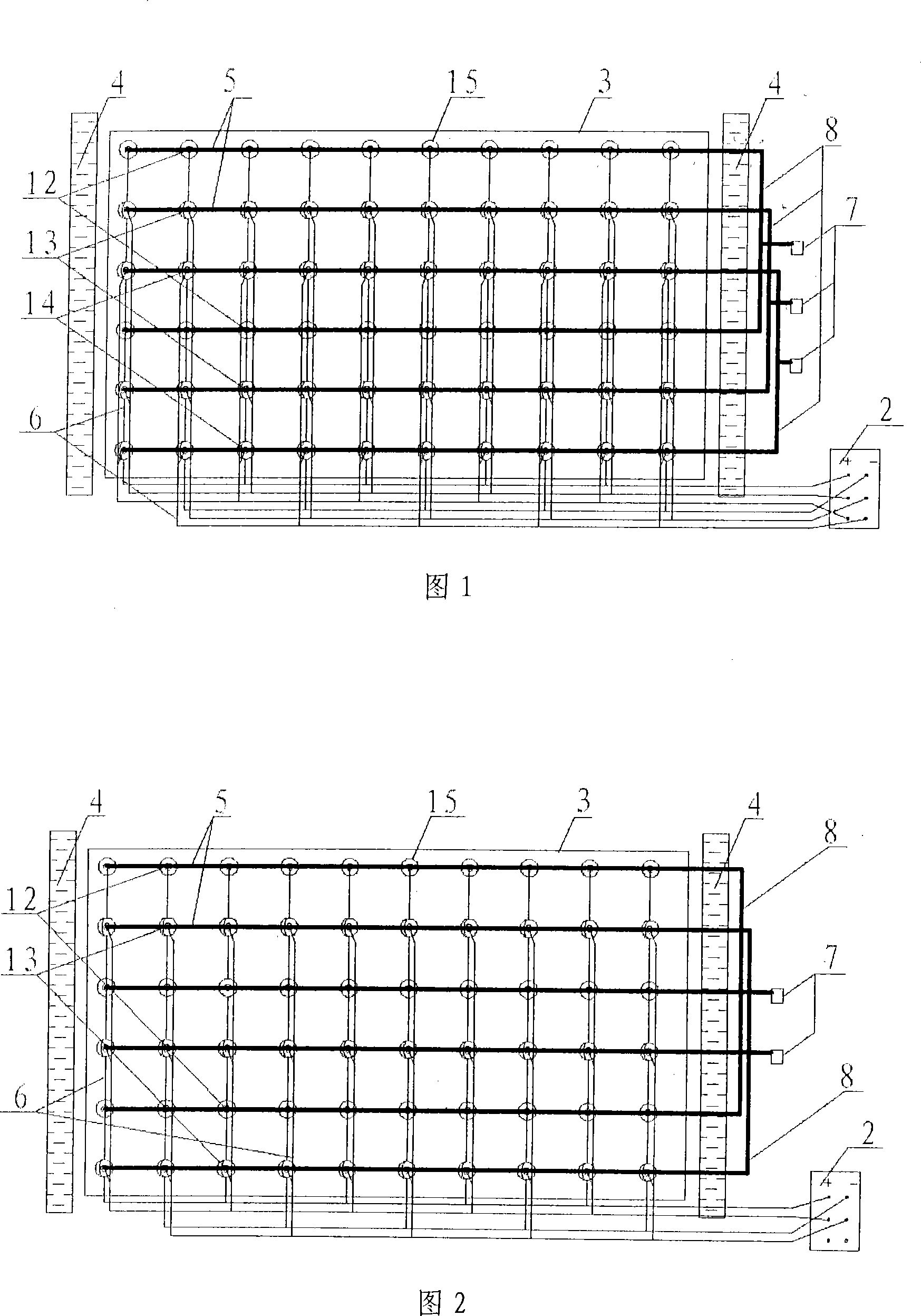
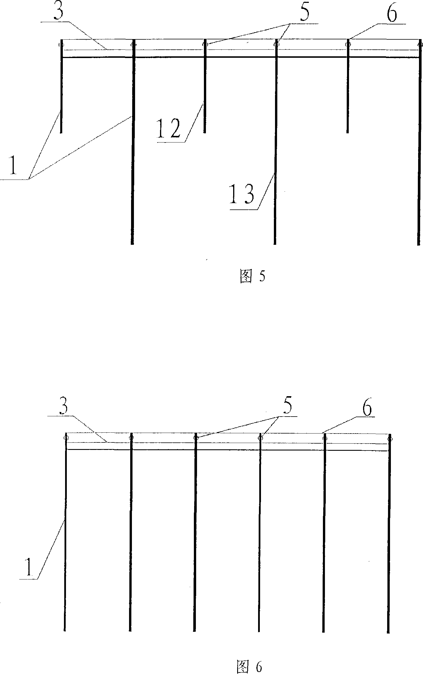
[0069] Embodiment 1: See accompanying drawing 1, accompanying drawing 4, accompanying drawing 7, accompanying drawing 8, and accompanying drawing 9 shown,

[0070] At a test site in Zhejiang, the treatment depth is required to be 11m

[0071] 1. Roughly level the site after entering the site, remove sharp objects, and carry out the construction and lofting of the composite pipe position on the flat surface according to the mesh distribution of the mesh cap eyelet film. The mesh spacing is set to 0.5 meters.

[0072] 2. Carry out detailed exploration of small screw drilling in the test area, and drill to a depth of not less than 11 meters below the surface. Due to the small area of ​​the test area, 25m×25m grid holes are used for small screw drilling detailed exploration, and well prepared Record. Find out the embedment depth and thickness of various soil layers in the test area, so as to know the soil properties, soil water content, permeability coefficient and endowment stat...

Embodiment 2

[0087] Embodiment two: see accompanying drawing 2, accompanying drawing 5, accompanying drawing 7, accompanying drawing 9, accompanying drawing 10 and accompanying drawing 11 shown,

[0088] Same as Example 1, in a test site in Zhejiang, the treatment depth is required to be 7m

[0089] 1. After entering the site, the site should be roughly leveled, sharp objects should be removed, and the position of the composite pipe should be set out on the flat surface. The distance between the composite pipes should be set at 0.5 meters.

[0090] 2. Carry out detailed exploration of small screw drilling in the test area, and drill to a depth of not less than 7 meters below the surface. Due to the small area of ​​the test area, 25m×25m grid holes are used for small screw drilling detailed exploration, and well prepared Record. Find out the embedment depth and thickness of various soil layers in the test area, so as to know the soil properties, soil water content, permeability coefficient...


PUM


Abstract

The invention discloses a covering composite vacuum electroosmosis and heavy tamping method for the groundwork reinforcement and a device thereof, and aims to provide a groundwork treatment method and a relevant device, and in particular a complete groundwork treatment method for the large-area soft soil with the penetration factor less than 10<-5>cm/s, and a device thereof. The device of the invention adopts a composite pipe and a holed redundant film or a reticular multilens film. With the method of the invention, the composite effect of the multi-layer electroosmosis and the multi-layer vacuum dewatering completely covered and sealed under the holed redundant film or the reticular multilens film replaces the single effect of electromomosis and vacuum dewatering, and the heavy tamping with the medium and low energy covered under the sealed films replaces the direct medium and low energy heavy tamping. The invention is provided with the advantages of the equilibrium treatment, the convenient construction, the short construction term, the high performance-cost ratio, and so on.

Description

technical field [0001] The invention relates to a covering-type composite vacuum electroosmosis and dynamic tamping reinforcement method and its device, which relate to a large-area shallow and deep soft soil foundation treatment method and its device, especially suitable for sites with low bearing capacity and general deformation requirements Soft soil foundation reinforcement. Background technique [0002] At present, in terms of vacuum electroosmosis and dynamic compaction technology, there is a patent of the China Patent Office Application No. 200710020427.8 Vacuum electroosmosis precipitation and low-energy dynamic compaction deep reinforcement method and device; this construction method is currently only available on sandy soil with a thickness of 1 to 2 meters on the surface It has been successful in small-scale engineering projects that are covered and not in rainy seasons. The patent has the disadvantages that the electroosmosis process only performs electroosmosis...

Claims


Application Information

Patent Timeline
IPC IPC(8): E02D3/00E02D3/11E02D3/02E02D3/10E02D3/046
Inventor 陈江涛唐劲柏杨宇文
Owner 陈江涛
Why Eureka
Try Eureka