Net band transmission type vacuum continuous drying device and net band transmission type drying device

A drying device and transmission-type technology, which is applied to drying solid materials, heating to dry solid materials, and non-heating to dry solid materials, etc., can solve the problems of material grain skin cracks, insufficient inner dryness, and large space size, etc. To achieve the effect of ensuring drying consistency, wide application range and low cost

Inactive Publication Date: 2008-05-28
COFCO ENG & TECH ZHENGZHOU +1
View PDF1 Cites 19 Cited by
  • Summary
  • Abstract
  • Description
  • Claims
  • Application Information

AI Technical Summary

Problems solved by technology

The dryer adopts the structural form of upper and lower multi-layer conveying mesh belts. Its drying process is long and it uses flowing hot air to dry, but its thermal efficiency is not high. In addition, there are certain defects: each layer of conveying mechanism is set separately, resulting in space The size is large, the structure is complex, and the cost is high; in addition, the use of hot air drying is prone to defects such as cracks on the surface of the grain and insufficient dryness of the inner core

Method used


Image

  • Net band transmission type vacuum continuous drying device and net band transmission type drying device
  • Net band transmission type vacuum continuous drying device and net band transmission type drying device
  • Net band transmission type vacuum continuous drying device and net band transmission type drying device

Examples


Embodiment 1

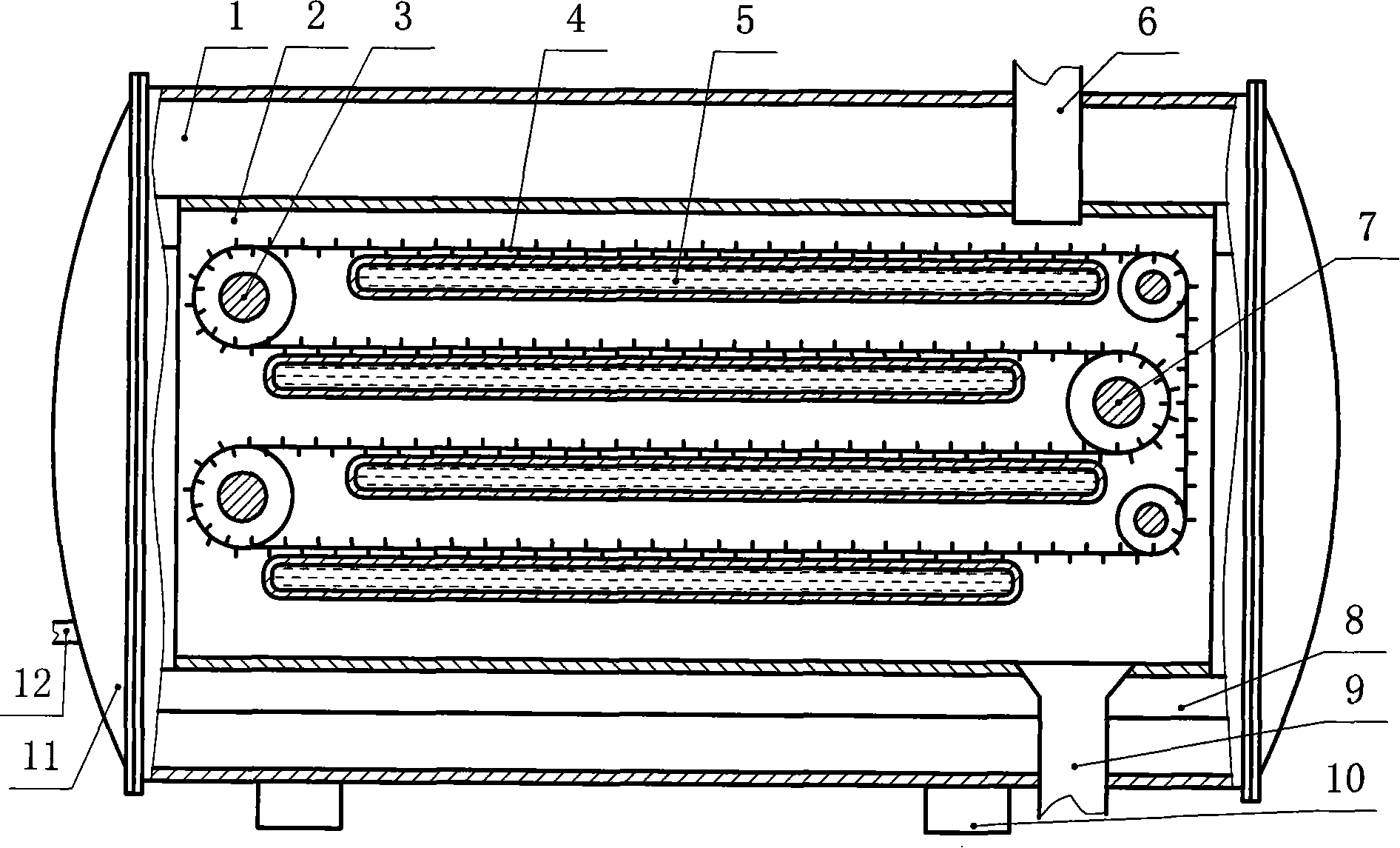
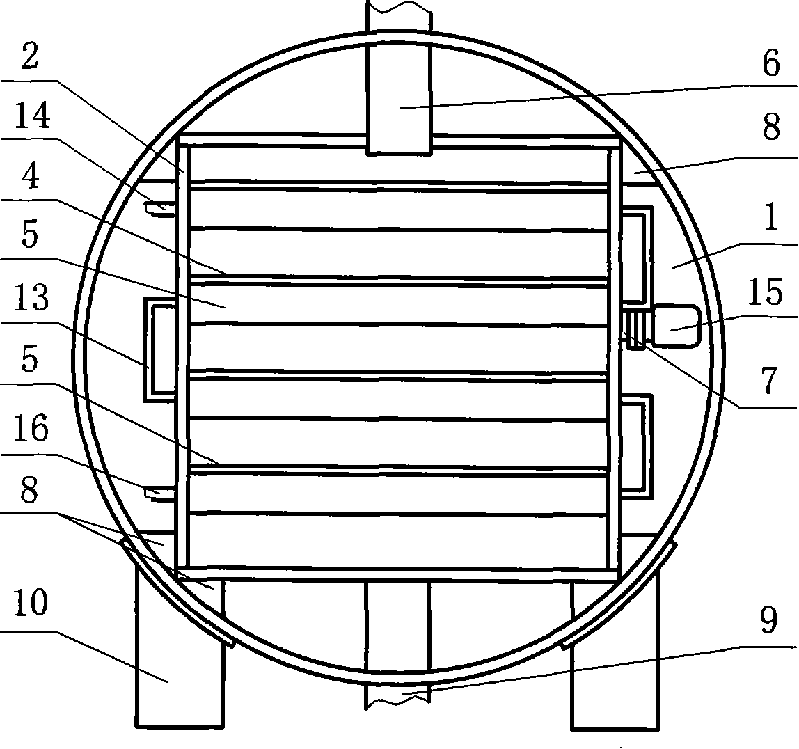
[0032] Embodiment one: see figure 1 , figure 2 , image 3 , Figure 4 , among the figure, the net-belt transmission type vacuum continuous drying device contains cylindrical shell 1, and the two ends of cylindrical shell 1 are respectively provided with spherical end cap 11, and one end cap (also can be on the body wall of cylinder Above) is provided with a suction pipe 12, the suction pipe 12 is connected to a vacuum pump, the axis of the cylindrical cylinder 1 is placed horizontally, a square silo 2 is set inside the cylindrical cylinder 1, and the two body walls of the square silo 2 There are four layers of flat water pipes 5 installed between them, and the uppermost flat water pipe 5 communicates with the water inlet pipe 14, the lowermost flat water pipe 5 communicates with the outlet pipe 16, and the middle flat water pipe 5 realizes end to end through the connecting pipe 13. Connected, so that the flow path of the water flow is a turn-back bow shape, and the water i...

Embodiment 2

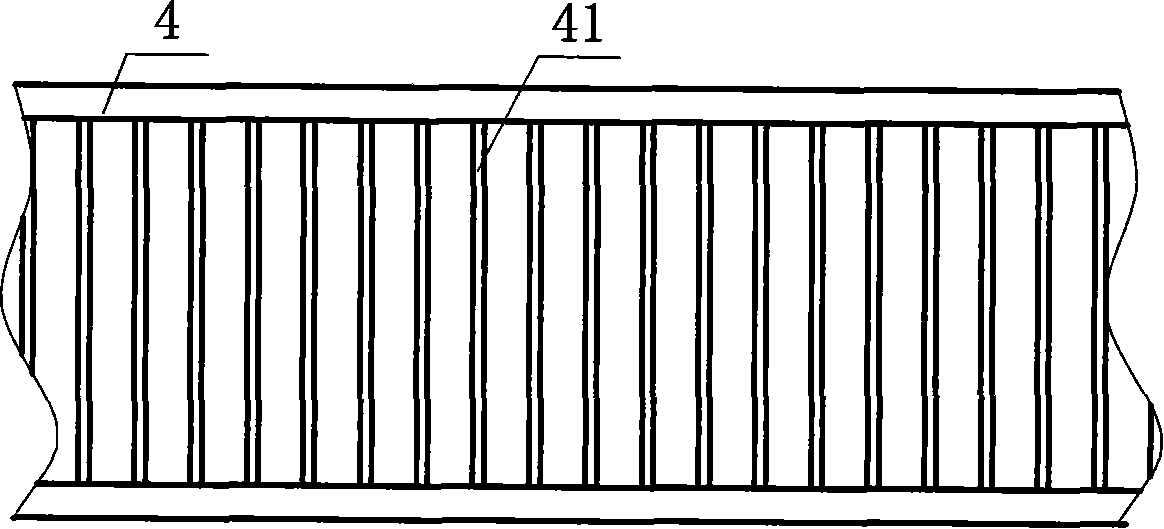
[0037] Embodiment two: see Figure 5 , Image 6 , the present embodiment is basically the same as Embodiment 1, and the similarities will not be repeated. The difference is that the specific structure of the endless mesh belt 4 is different. In the present embodiment, the endless mesh belt 4 contains two toothed conveyor belts, The two toothed transmission side belts are meshed with the gears at both ends of the rotating roller respectively, and a rotating plate is arranged between the two toothed transmission side belts, and a certain number of discharge holes 42 arranged according to a certain rule are arranged on the rotating plate , so that the material falls on the surface of the flat water pipe, suitable for drying granular materials.

Embodiment 3

[0038] Embodiment three: see Figure 7 , the present embodiment is basically the same as Embodiment 1, and the similarities will not be repeated. The difference is that the structure of the endless mesh belt 4 is different. In the present embodiment, the endless mesh belt 4 contains two toothed conveyor belts, and Two toothed conveying side belts mesh with the gears at both ends of the rotating roller respectively, and a flat net is installed between the two toothed conveying side belts. The mesh 43 on the flat net is convenient for materials to fall on the surface of the flat water pipe, which is suitable for particle packaging. Material drying.


PUM


Abstract

The invention discloses a mash belt transfer type vacuum continuous drying apparatus and a mash belt transfer type drying apparatus, which comprises a cylindrical barrel, a spherical cap-shape end cover, and an evacuating pipe, wherein the cylindrical barrel is horizontally arranged, a square silo is sleeved in the inner cavity of the cylindrical barrel, a certain number of floors of flat-type water pipes are mounted between two body walls of the square silo, and the flat-type water pipe which is on the highest layer is communicated with a water inlet pipe, and the flat-type water pipe which is on the lowest layer is communicated with a water outlet pipe, the intermediate flat-type water pipes are communicated end to end, and water glide path is led to take zigzag-shape arch type. A certain number of turn rollers which are regularly arrayed are mounted between the two body walls of the square silo, the turn rollers which are connected with a power mechanism are sleeved with ring-shaped mash belt, which leads materials on surface of the upper layer of the flat-type water pipe to convey to the surface of the lower layer of the flat-type water pipe, two lateral side of adjacent flat-type water pipes are alternatively arrayed respectively, and a feed inlet and a feed outlet are respectively arranged on the two sides of the adjacent flat-type water pipes which penetrates through the cylindrical barrel and the square silo.

Description

1. Technical field: [0001] The invention relates to a drying device, in particular to a mesh-belt-driven vacuum continuous drying device and a mesh-belt-driven drying device. 2. Background technology: [0002] my country is a large agricultural country, and the output of crops is huge. If they are not stored well, they will deteriorate. Therefore, it is necessary to reduce their moisture content before storage. At present, the traditional drying method mainly adopts hot air drying equipment, which makes the hot air pass through the crop particles under normal pressure to evaporate its moisture. The drying methods are usually cross flow, mixed flow and forward (counter) flow, but this drying method , it is easy to damage the inherent quality of crops. Taking dry corn as an example, the temperature of hot air is generally 120-160°C, while the natural temperature in the dry season in Northeast China is -5--30°C. Due to the huge temperature difference, the corn is dry During th...

Claims


Application Information

Patent Timeline
Patent Type & Authority Applications(China)
IPC IPC(8): F26B17/04F26B7/00F26B5/04F26B3/20
Inventor 张志军唐学军夏朝勇李军五郭兴群
Owner COFCO ENG & TECH ZHENGZHOU
Why Eureka
Try Eureka